Product Detectors
Product detectors are used to detect Morse (CW) and single sideband (SSB) signals by mixing those signal with the output of a local oscillator. The resulting audio will be at a relatively low level and will require filtering and amplification before it can be heard.
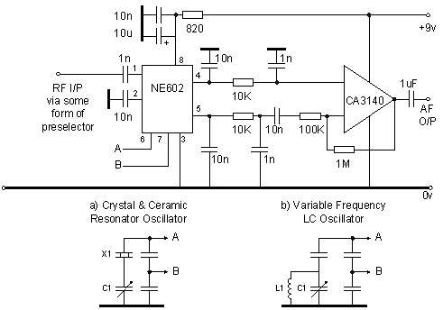
1. Active Detector
This circuit has sufficient gain to be used as either a product detector or a direct conversion receiver (DC Rx). The first set of notes apply to both applications, the second only to a DC Rx.
General Notes:
- The NE602 contains both the mixer and oscillator functions required for a product detector and the mixer section has around x6 (16dB) gain.
- The value of the 1uF capacitor in series with the AF output from the CA3140 will be determined by the input impedance of the following stage. The CA3140 op-
amp will not drive low impedance phones. - The gain of the op-
amp as shown is approximately x10 (20dB). - Roll-
off of the RC network between the mixer and op- amp should start around 3KHz. Shunt filter capacitors should be polyester, decoupling capacitors can be ceramic. - C1 will be around 47pF for crystal oscillator. Feedback capacitors between A, B and 0v will be around 150pF for 9MHz. The value for other frequencies and the tuneable version will depend on the frequency and band coverage that is required. Consult the NE602 data sheet.
- Do not let the voltage on pin 8 of the NE602 exceed 8v. The 820ohm resistor should provide sufficient voltage drop but a 6v low power regulator (78L06) could be used instead.
- The dynamic range of the NE602 is fairly low so some form of manual or automatic gain control will be required.
- This detector is only suitable for SSB/CW.
- When used as a product detector with preceding signal processing stages the gain of the CA3140 op-
amp may need to be reduced or the CA3140 could be left out entirely and the audio output from the NE602 connected directly to the audio filter mentioned in the next paragraph. - Some low frequency and high frequency roll-
off in the audio range is provided by this circuit but additional frequency shaping is recommended for best results - see the additional AF Band Pass Filter which is elsewhere on this site. - The 9v supply must be hum free.
- All resistors should be 5%, 250 or 330mW carbon film type.
- 1n and 10n should be 10%, 50vdc ceramic single or multi-
layer types. Note that +80- 20% capacitors are suitable for de- coupling but not for audio filtering or coupling. 10n may be polyester. - Pins 1, 5 and 8 on the CA3140 should be left unconnected.
- The CA3140 is a CMOS device that is susceptible to damage by electrostatic charge so handle with care.
- This circuit should work with medium to high impedance (600-
2000 ohms) headphones but will require an additional amplifier for use with low impedance (4ohm) headphones or a loudspeaker. - The NE602 may be replaced by the SA602.
DC Receiver Notes:
- An RF preselector has not been shown. Try a one section tuned circuit to start. Note that the input impedance of the NE602 is around 1K5 ohms so do not connect to the top of a tuned circuit but tap down to retain a reasonable loaded Q.
- Keep the wiring around the oscillator section (NE602 pins 6, 7) screened or well away from the aerial wiring (pin 1) to reduce the amount of oscillator leakage reaching the aerial and irritating other local band users.