Power Supplies (Low Voltage)
|
Ref |
Value |
Description |
Ref |
Value |
Description |
|
R1 |
1K |
330mW carbon film |
C1 |
100n |
Ceramic capacitor +80- |
|
R2 |
10K |
330mW carbon film |
C2 |
100n |
Ceramic capacitor +80- |
|
R3 |
1K5 |
330mW carbon film |
C3 |
4,700uF, 25v |
Electrolytic capacitor |
|
D1 |
LED |
Standard 10mA LED and holder |
C4 |
1,000uF, 15v |
Electrolytic capacitor |
|
D2 |
50v PIV, 1Amp |
1N4001 or similar |
T1 |
|
Mains transformer, 240v primary, 15v 1A secondary |
|
D3 |
LED |
Standard 10mA LED and holder |
F1 |
250mA |
Slow blow 20mm fuse and holder. Terminals should be sleeved after wiring. |
|
BR1 |
50v PIV, 1Amp |
Bridge rectifier or four discrete diodes (1N4001 or similar) |
F2 |
30V, 1A DC |
Single pole single throw toggle switch |
|
IC1 |
7812 |
12v, 1A maximum regulator IC mounted on a suitable heatsink |
S1 |
250V, 1A AC |
Single pole single throw toggle switch. See note 7. |
Notes:
- C1 and C2 should be connected to IC1 via short leads to prevent HF oscillation.
- C1 and C2 may be wide tolerance types as their precise value is not critical in this application.
- IC1 should be mounted on a vertical heatsink to keep it cool. Note that the tab on the IC is connected to the 0v pin so an insulating washer kit and thermal transfer paste may be required if the heatsink is not at 0v.
- The enclosing case, if metal, should be connected to mains earth but both output lines may be floating.
- If the mains transformer T1 has an electrostatic screen, as shown, then it should be connected to mains earth.
- An additional regulator IC and de-
coupling capacitors may be added to provide a 9v output. If the resulting total load current is greater than 1 Amp then all of the one amp rated components must be up- rated accordingly and the 4,700u capacitor increased in value. - S2 may be a double pole, single throw toggle switch with the additional switch in the neutral line.
- All mains voltage wiring should use adequately rated wires and solder joints should be sleeved to minimise the risk of electric shock if working on the unit with power applied. When construction and test is complete the entire unit should be fully enclosed so that all high voltage connections are not accessible.
- A printed circuit board is not absolutely necessary but all components and wiring must be firmly fixed in place.
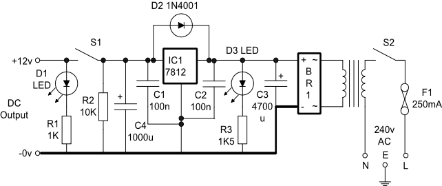
- Diode D2 will be illuminated when the mains is present and switched on and diode D1 will be illuminated when the output is switched on and 12V is present on the output terminals.
- The mains lead must have three cores and be held in place with some form of captive grommet or cable clamp. Do NOT rely on solder joints to retain this cable.
- If a higher output voltage is required, say 13.5v, then two series connected silicon diodes may be inserted in the common lead of IC1 (cathodes towards the 0v line) but the main transformer secondary voltage may need to be increased by a similar amount. Try your existing transformer in this configuration at full load first to see if it is adequate.
1. The following circuit is a simple, low cost, mains powered supply that will provide a stabilised output of 12 volts at up to 1 amp DC.
2. The following circuit shows how an emitter follower may be used as a current amplifier to provide a simple semi-
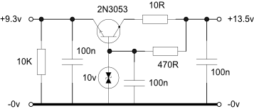
The 10R resistor provides a simple form of current limit in the event of a short circuit across the 9.3v rail.
Decoupling as shown is mainly for RF purposes but additional larger value capacitors may be used if the incoming line is very noisy.
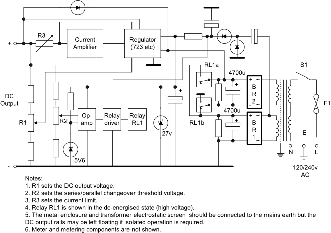
3. A simple solution to a wide voltage range adjustable regulated power supply without excessive dissipation in the current amplifier is to use a transformer with two identical but isolated secondaries and two sets of rectifiers and smoothing. On low voltage the secondary supplies are connected in parallel and on high voltage they are connected in series. The changeover can be automated by using an op-
The op-
I developed such a power supply for bench applications many years ago with no problems and the basic block diagram is shown below. The maximum output current is a function of the current amplifier, transformer and diode ratings. A reverse protection diode (1N540n) may be connected between the two output lines if required.