Solid State Circuits 18 -
The circuit below shows a single stage AGC system at 9MHz. The attenuator is comprised of a series resistor and two shunt PIN diodes. The attenuator is followed by a high input impedance cascode amplifier which may be made from discrete components as shown or a dual gate MOSFET. The purpose of the high input impedance is to minimise the losses due to the series resistor.
The decoupling capacitors are suitable for use at or close to 9MHz and should be increased in value for use at significantly lower frequencies. PIN diode BA479 is fine at 9MHz or higher but has insufficient recovery time for significantly lower frequencies.
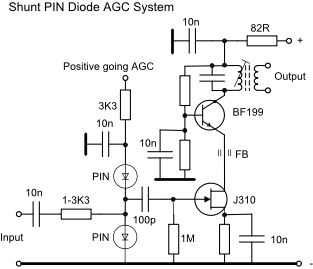
The typical gain at 9MHz was 33dB and the ferrite bead was required to prevent instability at VHF.
The AGC voltage is typically 0 -
Three stages have been cascaded in a well screened enclosure and on double sided PCB to obtain 110dB of gain and a similar level of gain control. To maximise the signal to noise ratio the AGC should be applied progressively from the later stage to the earlier stage.