Notch Filter
When measuring harmonic or other spurious outputs from a power amplifier it is necessary to attenuate the level of the fundamental in order to prevent overload of the spectrum analyser input circuits and the consequent generation of more harmonics than are actually present in the signal to be measured.
The following notch filter covers 1.8 -
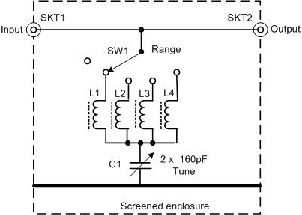
Each of the inductors is wound on an iron dust core of 0.5inches diameter. The lowest frequency range uses a pair or red coded cores stacked together. The next higher frequency uses a single red core and the two highest frequency ranges use yellow coded cores.
What is important is to use a rotary switch that shorts out the unused inductors to prevent spurious resonances afftecting the measurements but not the open switch position. The switch has one open position that isolates the inductors from the signal line and the connecting link between the two sockets is relatively wide copper strip to minimise its inductance.
This circuit should achieve a minimum notch depth of 20dB on the highest and lowest frequencies and typically 30dB on the rest which effectively increases the dynamic range of the analyser.
In use, the filter is inserted in the signal line between the sampling head and the spectrum analyser, in my case a Bird 43 through line wattmeter with a -