Low Cost Design Techniques
Doing ‘more with less’ is a very laudible aim which designers work towards but it requires a lot of care to ensure that the resulting side effects do not spoil the overall design. There is a practical limit to what can be achieved with a few valves or semiconductors and a handfull of components and once the law of diminishing returns is reached then the risks of failure become much higher.
Projects must be tested and measured to ensure that they do not cause more problems than they solve. For example, spurious responses must be adequately suppressed to ensure that they do not cause problems to the emergency services, broadcast users or other band users. There is no excuse and in any case it is a false economy to leave out the appropriate filters just to save a few pennies/cents etc on the overall costs.
The following design overviews are suggestions on how low cost designs with adequate performance figures might be implemented.
1. Direct Conversion Techniques
The main challenge here is to ensure that the reaction/regeneration detector or receiver local oscillator signal is not allowed to reach the aerial where it could cause interference to other local users. Filtering will not work as the detector / local oscillator is on the same frequency as the receiver so the two main solutions to this problem are to use a balanced circuits and/or an RF amplifier. Both solutions will attenuate the unwanted signal but the latter will also increase the overall sensitivity so care is required to ensure that the detector / mixer is not overloaded. Screening will also assist in reducing the spurious radiation.
2. Simple Superhet Techniques
In this instance the local oscillator is spaced away from the receive frequency by the intermediate frequency (IF) but it may still reach the aerial if there is insufficient screening, the mixer is not balanced and/or there is no RF stage. Generally there is no need for an RF stage on the lower HF bands due to the presence of sky noise and man made noise but it may help on 14MHz and above.
3. Transmitter (and Receiver) Filtering
Assuming that there is no spurious instability, there are three main sources of predictable spurious responses in a transmitter:
- Oscillator and mixing products in a superhet based circuit. These can be minimised by adequate control of the signal and oscillator levels, correct termination of the mixers and attenuated using band pass filters immediately after the mixer and before the power amplifier stages. The selectivity of the RF filters will be determined by the IF in use -
the lower the IF the more selective filtering will be required. - Harmonics generated in the power amplifier or driver stages, even if linear, which must be attenuated to a low level before reaching the aerial. These can be attenuated using a low pass filter after the final amplifier.
- Inadequate screening between the internal circuits and the aerial socket.
In the first two of the above cases, multiband operation will generally require filters for each band or groups of bands and some of these are applicable to the receiver as well as the transmitter.
To attenuate the amplifier harmonics there is a choice of filter topologies including Butterworth (constant k), Chebyshev, Bessel and Elliptic. The easiest is probably the Butterworth type with a flat passband response and relatively simple design equations. If a steeper attenuation response or a stopband notch is required then an ‘m’ derived section may be used.
Chebyshev filters can have a steeper attenuation response above the cutoff frequency but at the expense of more passband ripple so a compromise is always required.
3a) Band Pass Filters
Shown below are two basic forms of band pass filters usable in both receiver and transmitter:
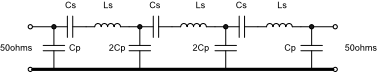
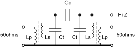
This filter is comprised of three identical resonant sections with low input and output impedances. Each resonant circuit is Ls in series with Cs with Cp, which provides the coupling between each section, typically 5 -
This filter is comprised of two tuned circuits Ls//Cp coupled together by capacitor Cc. Inductor Lp is a low impedance coupling winding. The high impedance output would typically be used to drive a MOSFET or similar RF amplifier. Cc is typically 2% to 10% of Ct depending on the required bandwidth. More sections may be used if required.
3b) Low Pass Filters
These are primarily used in the output of the transmitter but may help to attenuate the superhet receiver image if it is on the high side of the receiver frequency.
The above two section filter is a very simple Butterworth constant-
If a higher stopband attenuation is required then add an extra section or two.
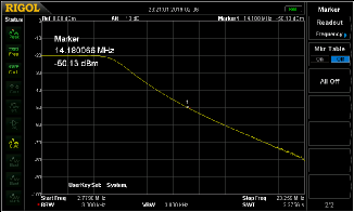
The -
Results: -
High power applications will require larger sized cores and thicker wire to minimise any heating issues.
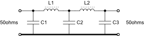
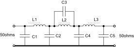
The above three section filter is a very simple two section Butterworth constant-
For 7MHz and m = 0.6 (which is a typical starting value) C1 = C5 = 354pF, C2 = C4 = 566pF, C3 = 186pF, L1 = L3 = 1.77uH, L2 = 1.06uH (14t 0.5mm on a T50-
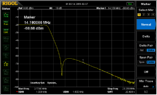
This places the notch at 10.81MHz which is a bit low for the second harmonic so the values will need to be recalculated for a higher value of ‘m’ or the centre section could be recalculated for a higher cutoff frequency to correctly place the notch.
The passband shape is very sensitive to changes in L2.
Results: -
-
Page under construction….