Logarithmic Detector -
This club project is divided into two parts -
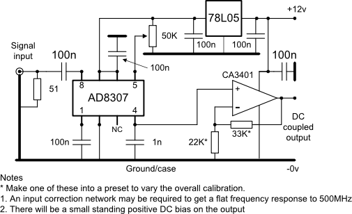
Both circuits are constructed using dead bug techniques with very short leads in the case of the log amp. The log amp input impedance is determined by a 51ohm chip resistor and the IC is wired directly in place without a socket.
1. Log Detector
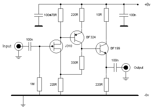
2. Impedance Converter
This circuit provides an input impedance of 1Mohm in parallel with about 10pF and may be used to drive the log detector circuit above when carrying out measurements on high impedance circuits.
The circuit is designed to work from an 8v supply (78L08 regulator from 12v inside the case) and provides a gain of approximately 1.6x and a frequency response extending to well above 30MHz. The low frequency cut-
The author powers this circuit from a 12v bench supply via a 78L08 regulator but the final choice is left to the individual constructor.
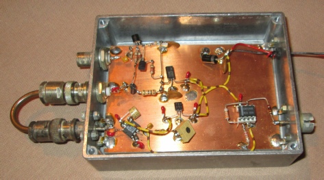
A picture of a completed unit built in ‘dead bug’ style is shown below:
The log amp circuit is at the lower left and the impedance converter to the upper left. The BNC sockets are from top to bottom: high impedance input, impedance converter output and log amp input. The socket on the lower right is the DC coupled output to the scope.