LC Bridge
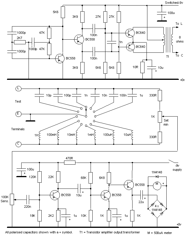
The above circuit is divided into three sections:
- 10KHz oscilator and power amplifier at the top
- Bridge in the centre
- Null detector at the bottom.
This is a simple circuit using mainly non-
The whole instrument should be built in a screened enclosure of some sort to minimise the pickup of external interference like mains hum or RF signals. Dead bug contruction will be fine.
The only critical components are those in the bridge which determine the overall accuracy of the finished instrument -
Polarised capacitors can be electrolytic or tantalum as preferred.
On completion of test, the Set Null control dial should be calibrated using accurate high tolerance components.
Capacitors to be tested are connected to terminals C and E. Inductors to be tested are connected to terminals E and L. Connect the component to be tested, switch on, set the sensitivity control for about 75% meter reading and then adjust the Set Null control for a minimum meter reading. Read the value off the calibrated dial. Switch off when finished to maximise battery life.