IF Filters 2
1. Filter Measurements
This section contains a series of measurements made on one example of each type of Heathkit SB-
a) All filters were terminated with 2000ohms and showed ripple values of not more than 2dB.
b) All frequencies in MHz.
c) The later SSB filter p/n 404-
d) All filters showed some signs of attenuation notches each side of the main response somewhere between -
e) All filters were also tested using L networks to match them to a 50ohm environment and this allowed the passband ripple to be reduced to about 1dB suggesting that there was some small, probably capacitive, reactance in the 2000 ohm test jig.
f) Health warning -
2. SSB Filter 404-
|
|
AM (wide) 404- |
SSB 404- |
CW 404- |
|||
|
Attenuation dB |
Low Side |
High Side |
Low Side |
High Side |
Low Side |
High Side |
|
- |
3.39418 |
3.39489 |
3.39407 |
3.39602 |
3.39525 |
3.39545 |
|
- |
3.394 |
3.39889 |
3.39397 |
3.39610 |
3.39522 |
3.3955 |
|
- |
3.39352 |
3.39946 |
3.39385 |
3.39622 |
3.39518 |
3.39564 |
|
- |
3.39281 |
3.40012 |
3.39369 |
3.39640 |
3.3951 |
3.39576 |
|
- |
3.39182 |
3.40095 |
3.39348 |
3.39660 |
3.395 |
3.39588 |
|
- |
3.39032 |
3.40203 |
3.39325 |
3.39684 |
3.39486 |
3.39604 |
|
- |
3.38785 |
3.40315 |
3.39298 |
3.39711 |
3.39468 |
3.39621 |
|
- |
- |
3.40425 |
3.39266 |
3.39750 |
3.39442 |
3.39635 |
|
- |
- |
3.40532 |
3.39246 |
3.39763 |
3.39402 |
3.39646 |
|
- |
- |
- |
3.39229 |
3.39785 |
- |
3.39652 |
|
Average stopband |
- |
- |
- |
|||
|
Notes |
Four crystals. Significant spurious responses at 3.54MHz, 3.575MHz and 3.688MHz. |
Six crystals. Slight spurious responses on the HF side. None worse than - |
Four crystals. Spurious responses on the HF side. None worse than - |
|||
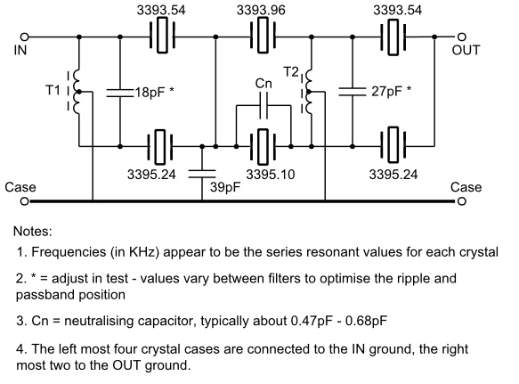
T1 total inductance = 65.5uH (resonates at 872.7KHz with 500pF).
Toroids have an outer diameter of 0.38inches and a thickness of 0.13inches. Material not known.
There was no evidence of any varnish on either toroid transformer which was surprising.
The internal crystal parameters are shown on the "Crystals for IF Filters" page on this web site.
This filter was purchased second hand and received with a fault in the form of a 30dB dip in the passband. Opening up the filter revealed a broken PCB track which has subsequently been repaired and the filter now exhibits the correct overall response.
3. SSB Filter 404-
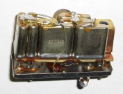
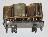
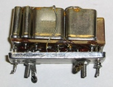
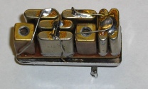
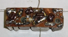
The lower right photo shows the repair to the broken track on the top right corner of the PC Board. The top and bottom connections are made to the case and the left and right hand connections are signal in and out.
As you can see, the filters can be disassembled but the critical trick is to melt the solder seal around the base without melting the component joints on the PCB. This means supporting the base of the filter and applying heat quickly to the outside of the base to soften the solder so that the cover may be pulled off. I use a plumbers gas blowlamp for this purpose. Once cool, repairs may be made and the unit resealed with a large soldering iron. Any scorched/burnt paint can be cleaned off and replaced. If you need to varnish any of the inductors then leave the filter open for several days to dry before resealing.
Right click on any photo and save it to your hard drive as required.
The AM and CW filters only used four crystals and their performance is not really adequate for today’s more packed bands. Modification / redesign is possible to add the additional two crystals as long as the pole zero frequencies are correct for the application. A new PCB will be required. Another option is to obtain and disassemble another AM/CW filter in order to use two of the crystals and a tuned circuit to create the additional filter section.