Heathkit -
I am often asked if the HW/SB line units can be converted for other HF / low VHF bands and my usual answer is ‘yes’ with some caveats, based on my own experiences with adding 160m to an SB101 and an SB401 and completely rebuilding an SB310 for all of the HF ham bands.
1. One option, if you must for whatever reason, is to modify your (only?) HW/SB unit for the required bands by losing some existing bands -
My preference for the other bands is to use the coils from the next band up and add capacitance to move the resonant frequency down to the required new band, for example use the 28MHz coils and add some fixed capacitance to move the resonance down to 24.9MHz for 12m and so on. The taps on the standard PA coil will need moving to optimise the PA loading and the best starting point is to move them halfway down to the next band tap.
It should be possible to modify the new HW/SB101 for 160m 30m, 17, 12m and use the remaining four band switch positions for 6m but care would be needed to ensure that sufficient RF filtering was provided on 6m to minimise spurious responses on both receive and transmit as Heathkit did not any form of balanced mixer for the RF conversion stages. Also bear in mind that the band oscillator is a parallel resonant type and crystals should be specified accordingly.
Modifying the switch wafers requires a vast amount of patience and access to a switch kit or similar collection of spare switch fittings -
You would need to have two sets of loudspeaker, microphone and key or find some way of switching one set between the two units.
2. Another possible solution is to modify an HW/SB101 for use as a second front end for an existing unit with the signal interconnections done at the tunable IF. This means that a lot of the internal circuitry in the new unit will no longer be required and can be removed, making room for a new internal power unit. A number of the front panel controls will no longer be required and there will be a technical issue to resolve relating to how the two units will be interconnected -
3. Alternatively the required circuitry (copied from the original) could be built inside an SB600 loudspeaker box with a new front panel containing the required controls -
4. New band crystals will be required as follows:
5. I think that it would be difficult to modify for the 5Mhz band as the internal VFO covers 5.5 -
Additionally, conversion to LF (137KHZ or 470-
6. I hesitate to suggest the use of a transverter in front of a standard HW/SB101 because the additional conversion process and gain would significantly increase the spurious responses and degrade the overall dynamic range. However, the increased VLF RF selectivity may make this option viable.
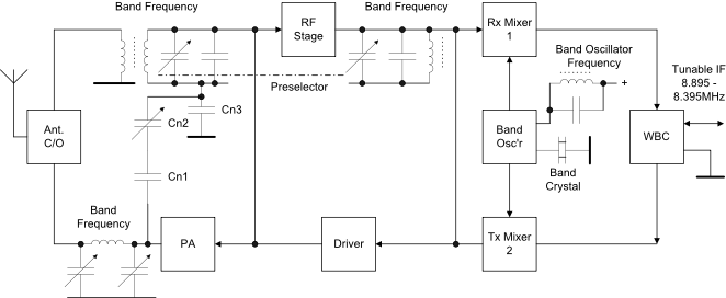
7. Shown below is a simplified functional block diagram of the SB/HW101 transceiver front end which is a bi-
NOTE: This is not a full schematic and significant components including DC isolating capacitors have been omitted in the interests of simplicity. The driver stage neutralising is not shown.
|
Lower Band Edge MHz |
Crystal Frequency MHz |
Lower Band Edge MHz |
Crystal Frequency MHz |
|
1.50 |
10.395 |
24.80 |
33.6950 |
|
1.80 |
10.6950 |
50 |
58.895 |
|
10.0 |
18.8950 |
50.5 |
59.395 |
|
18.0 |
26.8950 |
51 |
59.895 |
|
24.50 |
33.3950 |
51.5 |
60.395 |
|
Additional Capacitance |
Original Band |
New Band |
|
15pF |
28MHz |
24.5MHz |
|
21pF |
21MHz |
18MHz |
|
90pF |
14MHz |
10MHz |
Top Band: New tuned circuits will be required for the RF, mixer and band oscillator circuits. The RF and mixer circuits should use fixed tuning capacitors around 330-
The following table shows suggested values of additional capacitance to move the resonant frequency of the original RF and Mixer band coils down to the nearest lower WARC band. The formulae to calculate the new values is located on the Useful Formulae page.