Crystal Filter Test Jig
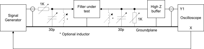
The following circuit shows a simple test jig that may be used to test most crystal filters.
Note:
- The signal generator should have a DC coupled narrow sweep external signal input and the oscilloscope should have a DC coupled X output
- The unity gain high impedance buffer is required to ensure that the minimum capacitance load is applied to the filter -
if you do not have one then a 10:1 scope probe may be used instead. - The oscilloscope should have a vertical frequency response that will pass the frequencies for which the filter is specified.
- A spectrum analyser and tracking generator may be used as an alternative to the signal generator and oscilloscope as long as the resolution bandwidth and scan speed can be made sufficiently slow for the filter bandwidth under test. If not then the displayed frequency response will not be correct.
If the filter requires purely resistive terminations then the optional inductors will be required to tune out the stray capacitances at the input and output points.
Connect up as shown, set the scope for 10mV sensitivity and the generator for 100mV output. Tune the generator around the filter frequency until an indication is seen on the scope. Select external FM and adjust the frequency deviation so that the filter passband is clearly visible. Now adjust the variable resistors and capacitors for the best filter passband response (least ripple) -
If zero pF is required then add the inductors and adjust them for resonance -
Reverse the filter and repeat the measurements to check if it is symmetrical or not.
If the resistors end up at maximum then they may need to be increased in value.
The termination impedance may now be estimated from the trimmer settings and measuring the resistor values with a test meter.If you have a lot of local RF interference then the jig may need to be screened.
Page under development….