CT82 Noise Generator
This instrument was manufactured for military use in testing HF receivers, radar IF amplifiers and metric radar receivers in the frequency range 15KHz to 100MHz and was also known as an A.P.67166. It contained a two diode noise generator, calibrated audio output power meter and mains power supply in a single case. The output impedance was switch selectable to 43, 75 and 400 ohms. A coaxial lead connected the noise head to the front panel.
I re-
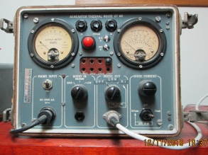
The photo to the right shows the front panel of the CT-
I do not use the AF power meter as it gave problems and I already have a Marconi AF power meter.
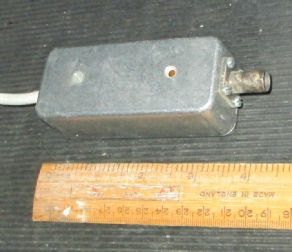
This photo shows the external noise generator head built into a small die cast box with a BNC connector at one end and the captive interconnecting cable at the other end.
The noise diode has a very limited operational life if run at full filament current so it should be kept as low as possible or switched off between measurements. The CT82 has three filament current settings -
Typical Noise Generator Circuit:
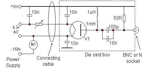
The 50ohm termination should be of good quality and low inductance, ideally a coaxial metal film type. However four solid carbon or surface mount resistors, two of 180ohms and two of 220ohms in parallel will produce an adequate termination up to at least 150MHz but may be more noisy than the metal film type. Connect one end of each resistor to a solder tag on each corner mounting of the coaxial socket and the other end of each resistor to the centre pin. Check the values of solid carbon resistors with an ohm-
The variable series resistor feeding the filament should have a sufficiently large maximum value to reduce the anode current to less than 1mA -
Note that the power supply uses a positive earth arrangement.
Click here for more information on the use of noise generators.