Solid State Circuits 16 -


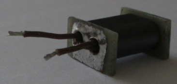
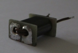
The photos below show a design for a 20W broadband RF transformer for use from 1.8 -
The brass tubing is soldered to the single sided PC board copper surfaces at each end, filed down smooth and then deburred with counter sink bit. The two turn winding may then be put in place. One of the PCBs has the copper area separated with a small gap, the other PCB copper surface is continuous.
PTFE insulation is required to prevent it softening or melting during construction (soldering) and operation. This type and size of transformer may be used to drive a pair of push-
The completed transformer is soldered down on the surface tracks of the power amplifier board and lacing twine or a tie wrap may be used for extra mechanical stability. To ensure a good fit on the motherboard the lower endges of the two end PCBs on the completed transformer should be parallel which can be achieved using a fine file at least as wide as the PCB cheeks. The bandwidth should be adequate to cover 1.8 -
Two of these transformers were connected back to back with a single compensation capacitor and showed a frequency response of 1.5 -
Higher power transformers will require a larger core and possibly different turns ratios. Designs are available on the Internet up to at least 2KW. Power levels up to 100W are possible with the correct sized core and a 13.5v supply. Power levels above 100W are best implemented with 28v or 50v supply devices and may also use multiple amplifiers and combining transformers.
If you prefer to buy this type of transformer ready made there are a number online suppliers -