Automatic Gain Control
Concept:
Automatic gain control (AGC) which used to be called automatic volume control (AVC) is a mechanism to minimise the changes in receiver audio output when changes take place to the received signal level. This can be viewed as a closed servo loop and the overall performance is dependant on the bandwidth of the various receiver circuits. In particular is the effect of signal delays due to mode filters in the intermediate frequency (IF) chain. The narrower is the filter bandwidth the longer is the signal delay.
Modes like single side band (SSB) and Morse (CW) require the receiver AGC to respond very quickly to the leading syllable or character otherwise there will be a burst of high level audio output until the AGC can respond. The AGC must also hold up during gaps between syllables or characters which is different to the requirements for AM reception.
Early valve communication receivers used a single AGC line to control the receiver gain and this was based on the reception of amplitude modulated (AM) signals. This type of AGC configuration does not work well with SSB or CW signals as it does not respond sufficiently quickly.
Current receiver design thinking requires the gain between the aerial socket and the mode filters to be as low as possible followed by the filters and then whatever gain is required to activate the detectors and AGC system. This means that the gain after the filters could be as high as 100dB. In addition, to get a fast AGC response time the bandwidth of the stages providing that gain should be as high as possible resulting in a relatively high noise level at the detector(s).
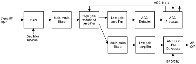
One solution to this conundrum is shown below:
This solution provides a high gain wideband gain controlled gain IF amplifier with the output split into two separate streams with the levels determined by the maximum drive levels into the noise filters. One goes to the AGC detector via an amplifier and the other one goes to a series of filters that pass each required mode signal but reduce the wide band noise levels and then on to a low gain amplifier and the appropriate detector.
The AGC processor has to provide one or more control outputs with the timings required to cater for any mode filters inside the control loops. The fast control is applied to the wideband amplifier which provides a very fast response to changes in signal level but is unaffected by the various mode filters as they are outside the control loop. Additional control lines may be required for circuits prior to the main mode filters with the appropriate time delays to cater for the signal delays inherent in those filters to ensure that the overall result is stable at all signal levels.
The gain of each low gain amplifier must be adjusted so that the AGC threshold occurs at the correct signal level and no distortion occurs at the AM/SSB detectors at maximum signal level. For full break-