Aerial Matching Unit for 1.8 -
1. A Classic HF Z-
The Z-
Some years back the author built a dual Z-
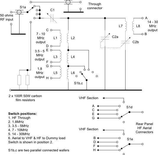
The version 2 HF section circuit is shown below.
|
Item |
Description |
Item |
Description |
|
C1 |
500pF maximum single section, variable capacitor held off the chassis with insulated mountings. An insulated shaft coupler must be used. |
L5 |
9t of 18swg, tapped every 3 and 6 turns with an ID about 0.4inch greater than L6. This inductor assembly must be fixed over the cold end of L6 with insulating spacers and a suitable adhesive. |
|
C2a/b |
250pF per section max value, double gang variable capacitor. |
L6 |
19t of 18swg with an ID of 1.6inch, turns spaced apart with 22swg wire which is subsequently removed. |
|
L1 |
6t 16swg 1.75inch ID, each turn spaced about 1/6" and mounted concentrically over the cold end of L2. |
L7 |
6t 18swg 1.25inch ID spaced apart to take a total of 1.25inch. |
|
L2 |
6t 16swg 1.25inch ID each turn spaced about 1/6inch |
L8 |
3t 18swg 18swg 1.75inch ID, each turns spaced 0.62inch apart. |
|
L3 |
6t 16swg 1.75inch ID spaced by 0.062inch |
S1 |
Heavy duty 5 pole 6 way rotary switch - |
|
L4 |
10t 16swg 1.25inch ID, with a total winding width of 1inch positioned in line with L2 |
|
|
Notes
ID = inner diameter.
The frequency coverage is dependent on the maximum to minimum swing of C1, C2 and the respective inductor values. A three to one frequency coverage requires a nine to one capacitance swing plus some contingency so it is recommended that any preset trimmer capacitors present on C1 and C2 be removed and wiring capacitance be minimised.
The impedance matching range is primarily dependent on the turns ratio of each pair of coils and the values of capacitors C1 and C2. If you have problems getting a good match then it may be necessary to adjust the turns ratio by increasing or decreasing the number of secondary turns.
For example, if the Z-
For transmitter powers up to around 25 watts "old fashioned" air-
The actual number of turns on each tuned inductor will depend on the tuning capacitor maximum and minimum values and your layout. It is best to prototype and test the coils before making the final versions. Each pair of coils for L1/L2, L3/L4 and L7/L8 should be supported using perspex or acrylic sheet and some form of low loss solvent based fixative e.g. polystyrene or acrylic cement. These supports can be attached to the chassis using long, tapped, insulated spacers. The relatively high number of turns on L6 will require a conventional low loss coil former -
S1b and S1c are two closely spaced switch wafers connected in parallel to cater for the circulating current in the tuned circuit, particularly with high powers.
The entire unit should be built in a metal box of sufficient dimensions to allow a spacing of at least one coil diameter between each coil and the nearest side of the box. Slow motion drives make for easier adjustment and perspex dials calibrated 0-
Click here to see photographs of the front and rear panels.
Click here to see a photograph of the original version 1 internals.
Click here to see a photograph of the revised version 2 internals.
Click here to download the version 2 coil support templates as a PDF file
Version 2 -
The picture here shows the finished rebuild of version 2. Changes from the original include:
- Much larger spaced HF tuning capacitors
- New HF inductors
- HF tuned circuit switch now has two wafers connected in parallel to reduce the losses
- All VHF connectors changed to BNC
- VHF SWR bridge now uses the HM-
2102 bridge (the HF bridge is from an HM- 102) - Revised VHF calibration controls
- All 50 ohm switches now have metal screens on both sides of each wafer
- Internal screened 50ohm dummy load for HF
- HF wire joins are either bound side by side or use 3/32 inch brass tubing for an inline joint and soldered -
this eases the problems of later disassembly and maintenance.
The revised schematic of the HF section is shown above. The VHF schematic is shown below.
How to Use a Z-
- See the connection diagram below.
- Switch the SWR Bridge to the dummy load.
- Key up, tune and load the transmitter for maximum output if these controls exist (probably only on older valve rigs as modern solid state rigs are broad banded).
- Ensure that the VSWR reading is showing 1:1 or very close i.e. very low reflected power.
- Reduce the power output to around 10-
25% of maximum so as not to strain the PA and de- key. You can achieve the same result by selecting AM if available on your rig. - Switch the SWR Bridge to the Z-
Match with an aerial connected. - Find a signal on your chosen band. Select the frequency range required on the Z-
Match and adjust both Z- Match tuning controls for strongest received signal strength. - Now find a clear frequency, key up the transmitter and adjust both Z-
Match tuning controls for minimum reflected power on the VSWR bridge i.e. SWR is 1:1 or very close. - Increase the output power to the required level and you are now correctly matched for that band.
- Dekey the transmitter and note the settings for future use to reduce tune-
up time.
Trying to adjust a Z-
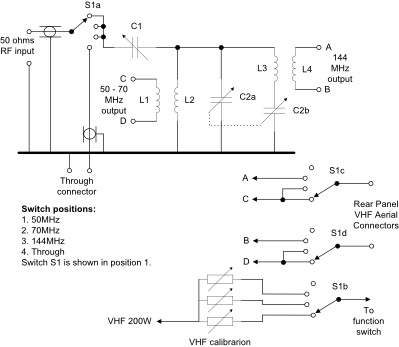
The VHF section shown right uses a very similar circuit to that of the HF unit although the component values are significantly less and no tuned circuit switching is required. C1 is a single section 3-

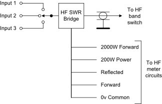
HF Input Selector
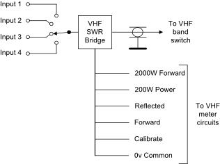
VHF Input Selector
The metering circuits are shared between the HF and VHF sections. The VHF section includes calibration controls to correct small differences in the frequency response of the VHF SWR bridge across the 50 -