Valve Transverter
Work on a prototype three band transverter resulted in a working transverter for 6m producing some 25W output for a drive level of a few milliwatts. The lineup consisted of:
- a solid state module containing two crystal oscillators for simplex and repeater operation
- E180F oscillator buffer stage
- Two E180F pentodes as a balanced transmit mixer
- 5763 driver stage on 300V and a 7984 pentode power output stage on 400V
- 6CW4 receiver RF amplifier followed by an E180F mixer stage
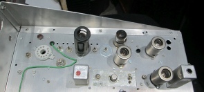
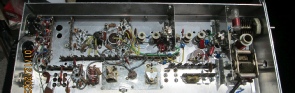
The photos below show oscillator module and the top and bottom views of the 6m section.
Space in this layout was a bit tight around the output stages and some changes would be required to ease the overall construction for which there was adequate chassis space.
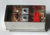
Oscillator module. A solid state (JFET) oscillator was chosen to provide much improved frequency stability compared to a valve oscillator. Although the output level from the oscillator is fairly low the E180F tuned buffer provides an adequate level of drive fror the receive and transmit mixers.
Top view with the PA stage (valve removed) on the left hand side. The aerial changeover relay is in the aluminium can near to the driver stage. The oscillator module fits on the top right hand corner of the chassis.
Underside view with the PA on the right hand side. The balanced mixer and five tuned circuits should provide a reasonable level of spurious response rejection as long as the mixer is not over-
Note that the 7984 has a 12V heater.
The E180F valves have an extremely high slope of 16.5mA/V and a low equivalent noise resistance of 330ohms so an interesting and useful device but care is needed with the layout to ensure stability.
The multi-