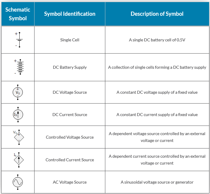
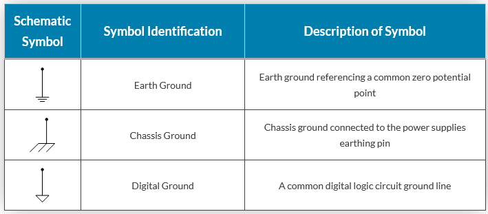
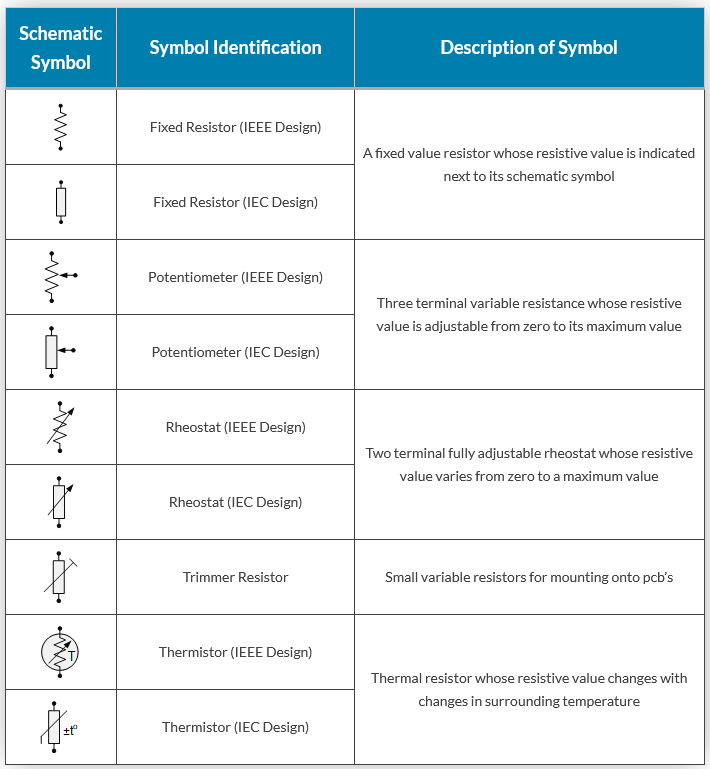
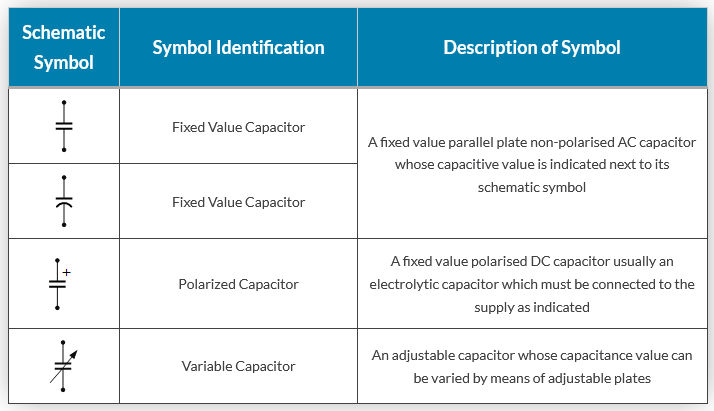
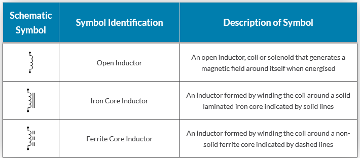
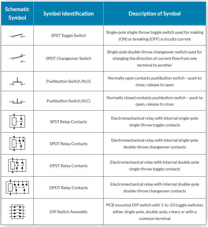
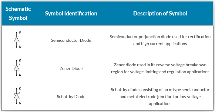
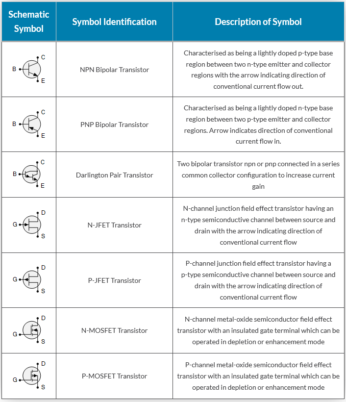
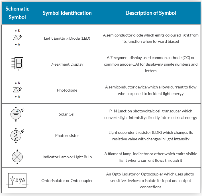
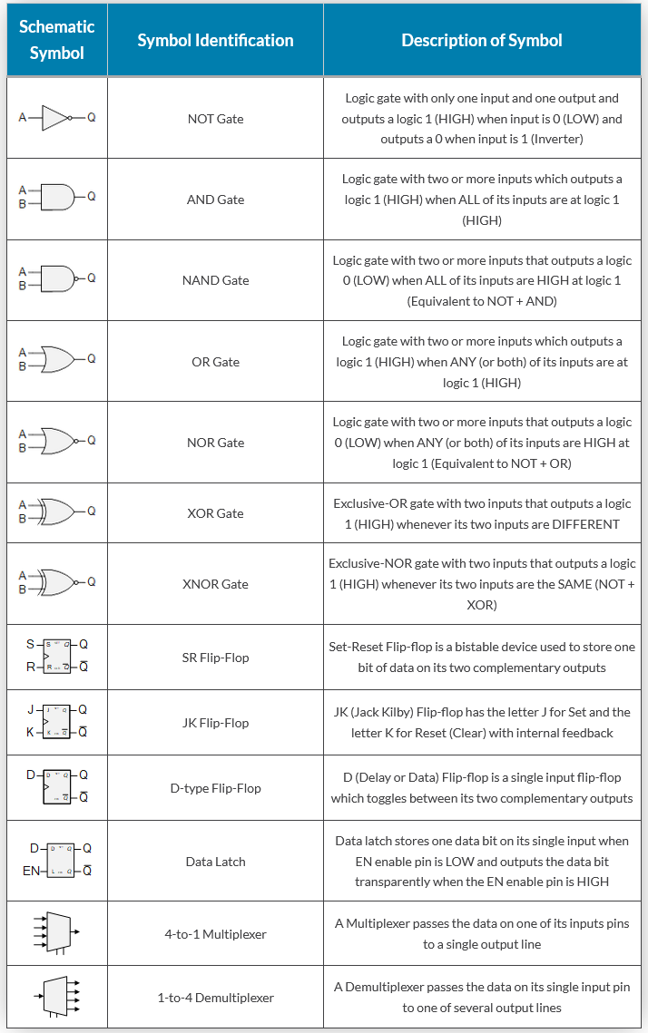
Circuit layouts and schematic diagrams are a simple and effective way of showing pictorially the electrical connections, components and operation of a particular electrical circuit or system. Basic electrical and electronic graphical symbols called Schematic Symbols are commonly used within circuit diagrams, schematics and computer aided drawing packages to identify the position of individual components and elements within a circuit.
Graphical symbols not only identify a components position but the type of electrical element too, whether its resistive, inductive, capacitive, mechanical, etc. Thus in circuit diagrams and schematics, graphical symbols identify and represent electrical and electronic devices and show how they are electrically connected together while drawing lines between them represents the wires or component leads.
A the connecting leads or pins of a component in a schematic diagram can be identified using letters or abreviations. For example, the connecting leads of a bipolar junction transistor, (BJT) are identified as E (emitter), B (base), and C (collector). Arrows are also used within schematic symbols to indicate the direction of convertional current flow around a circuit or through a component, or are used as part of their graphical symbol to show that the components has a variable or adjustable value. For example, a potentiometer or rheostat.
Although electrical components are represented by universally accepted schematic symbols, there are a number of variants and alternative symbols used throughout the world to represent the same electrical component or device. For example, the IEC (International Electrotechnical Commission) have one set of symbols, while the IEEE (Institute of Electrical and Electronics Engineers) have an alternative set of symbols for the same component.
The basic electrical and electronic graphical symbols presented here are the more generally accepted graphical symbols because of their common usage across a range of electrical and electronic fields. The individual graphical symbols below are given along with a brief description and explanation.
Updated 4 November 2021.