An example of their use can best explain by their operation. Take, for example an 80/40 meter trap dipole. The centre section of this aerial is a normal 40 meter dipole of conventional length. One end of each trap is connected to the ends of this dipole. The other end of the trap is connected to additional lengths of wire (typically 21 feet) to allow the complete aerial to resonate on 80 meters.
The resonant frequency of the traps should be the frequency you wish to use in the 40 meter band. The additional 21 foot lengths of wire should be adjusted so that the aerial resonates at your choice of frequency for the 80 meter band. Note that each leg of the dipole is only a little over 50 feet long making it about 20 percent shorter than a full sized 80 meter dipole.
On 40 meters, the traps have a very high impedance, effectively disconnecting the two 21 foot lengths of wire needed for 80. On 80 meters, the traps act as loading coils permitting the aerial to be shorter than a conventional 80 meter dipole.
The 80/40 meter trap dipole example will work on all bands (80, 40, 20, 15, and 10), but will work most efficiently on 80 and 40. If this sounds to good to be true (shorter aerial with multiple band performance), there are some compromises to be considered. On 80 meters even a full sized dipole cannot provide an SWR of less than 2:1 across the entire band. On 40 meters, we have the same problem to a lesser extent. A trap dipole exhibits an even narrower bandwidth than a full sized aerial. Still, if your use of these bands can be served with a 200khz to 250khz bandwidth, a trap dipole can be a good solution.
Another compromise of a trap dipole is the requirement for the traps. Conventional traps are constructed of high voltage transmitting type capacitors and heavy B&W miniductor stock. They are not particularly difficult to make, but the parts are expensive and they are subject to drift in frequency when exposed to adverse weather conditions. However, there is a method of building traps that is very inexpensive, can withstand full legal power limits, and is relatively stable under even the most adverse weather conditions.
The 1988 ARRL Handbook alludes to this method of trap construction but does not give any specific data. I have built a set of traps using this method and would like to share the information with anyone interested in home brewing a trap dipole.
My traps were built to be used in an 80/40 meter dipole as in the example given. The same method of construction can be used for other frequencies with the turns reduced to cover the higher frequencies.
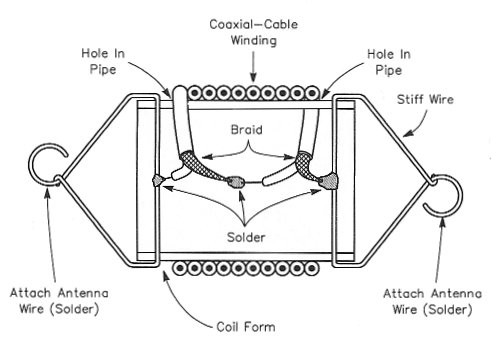
The method of construction alluded to in the handbook uses a coil of coax to form the tuned circuit of the trap. The shield of the coax forms the coil. The centre conductor of the coax on one end of this coil is connected to the shield at the opposite end. This allows the capacitance between the centre conductor and the shield to act as the capacitance that resonates the assembly.
Aside from the low cost, this method reduces resistive losses in the coils to an absolute minimum. The shield portion of the RG62AU coax I used is electrically equivalent to using quarter inch copper tubing. The capacitor formed by this assembly is capable of withstanding several thousand volts of RF allowing the use of high power on 40 meters. Although I used RG62AU, RG58 or RG59 would serve as well. RG8 may also be usable, but it's stiffness might require a larger diameter coil form and may result in a heavier assembly.
My traps were wound on two 6.5 inch long pieces of schedule 40 PVC pipe 1.25 inches O.D. I found that 20.5 turns would resonate at 7.050 MHz, my chosen 40 meter frequency. Each end of the PVC pipe was prepared by drilling two opposing holes in it about 0.25 inches in from each end. Solid number 12 copper wire was inserted through these holes and bent around the PVC to form a loop with the wire inside the pipe. These terminations were used to attach the aerial wire as well as provide a tie point for the coil of coax.
Each trap will require 80.5 inches (6.7 feet) of coax. Start with seven feet and trim it up to the frequency you want in the 40 meter band. Each length of coax is prepared by stripping about 2 inches of outer insulation from each end. The shield is unbranded and twisted at each end. The centre conductor at one end is stripped of insulation for a length of about 1 inch. Start your winding by drilling a hole just large enough to pass the coax through the PVC pipe. This hole should be located about 0.5 inches in from the end of the pipe. A close fit of the coax through this hole will help secure the winding until the holes are filled with epoxy.
Insert the end of the coax that has the centre conductor stripped through the hole and wrap the shield of the coax around the number 12 wire at this end. Solder the shield to the wire. Use a 50 to 100 watt iron and do it quickly so that the heat will not travel up the braid to melt the insulation to the centre conductor. Let the soldered connection cool completely before starting the winding. Now wind about 22 turns of coax onto the pipe. I estimate that 22 turns will resonate at the low end of the 40 meter band. If you are interested in the higher portion of the band, stop at 21 turns. Remember, you can always cut off coax to raise the frequency, but if you get too high in frequency, your best bet is to start over with a new length of coax.
Mark the pipe at the end of the winding and drill another hole in the pipe at this location to pass the coax. The close fit of the coax into this hole will keep the windings in place.
Prepare a length of wire. Hook-up wire #20, #18, #12, is adequate. Cut the wire to 6.5 inches in length. Strip off 1.5 inches of insulation from each end of the wire. Solder one end of the wire to the centre conductor of the coax at the end where you started your winding. Pass the wire down through the centre of the pipe and twist it's bare end to the coax braid where you finished the winding.
Pull the hook-up wire through the centre of the pipe so that the soldered bare end of the coax centre conductor is pulled down away from the soldered coaxial braid at the end of the coil where you started the winding.
Now you will need a grid dip meter to check the resonant frequency of the trap. Don't rely on the grid dip meter's calibration. Use a frequency counter or your communications receiver to verify the frequency. I found that by inserting the coil of the grid dip meter about 1/8th inch into the end of the PVC pipe an easily recognizable dip could be obtained. For your final frequency check you may want to reduce the coupling between the dip meter's coil and the trap. In my case I found a 50khz shift in frequency as I reduced the coupling. The dip obtained at the reduced coupling is the more accurate one. Also, make certain that your dip meter is on the right frequency range and that you have the receiver tuned to the fundamental frequency and not a harmonic. My grid dip meter had enough output to register an S9 +20db at the receiver with the receiver's aerial disconnected. Use the receiver's S-meter to zero in on the dip meter's output when determining frequency or zero beat as you would on an AM signal.
Your first frequency measurement should fall somewhere in the low end of the 40 meter band. If it doesn't, and if you did get a dip on the meter, you may be too low in frequency. If so, cut off about two inches from your winding and try again. In my case, I found that a one inch reduction in coax length resulted in an approximate 50khz frequency shift.
As you cut more and more coax from the winding, you will need to drill additional holes in the PVC for proper termination of the winding. The PVC is easily drilled. This cut-and-try method requires a little patience, but it is very repeatable. My first trap took me one hour to build. The second was done in 20 minutes.
The coax winding is tight and close spaced onto the PVC form. After your final frequency check, trim the finished end of the coax winding and solder the braid and the short length of hook-up wire to the #12 copper wire termination that you installed in the pipe at that end.
That completes the trap. Now all you have to do is build another one and solder the aerial wires to the copper wire terminations at each end of each trap.
Note that the number of turns required will only hold true for RG62AU coax. Other types of coax may well be used, but the turns required may vary.
Initially, I was a little concerned as to whether or not the end terminations I used would hold the strain of supporting the traps. The terminations have held through the weather conditions we have experienced in the last year very high winds. However, I would not recommend using anything less than schedule 40 PVC pipe.