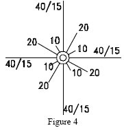
If you can’t copper-plate the backyard, the best approach is to run out as many radials as possible, each as long as possible around the antenna in all directions. Radials may be left on top of the ground however they should be buried for the sake of pedestrians and lawnmowers. How long should radials be? A good rule is no shorter than the antenna is tall because 50% of your losses will occur in the first 1/4 8 out from the antenna. If you have more than a dozen radials, they must be longer to get the most out of them which is why the professional services specifies 120 wires each .4 8 for AM broadcast stations—the equivalent of a zero-loss ground plane. Obviously, for most ham work this would be overkill. In some cases wire mesh (i.e. chicken wire) may be used as a substitute for radial wires and/or a ground connection, the mesh or screen acting as one plate of a capacitor to provide coupling to the earth beneath the antenna. It should be noted that a ground rod is useful only as a d.c. ground or as a tie point for radials. It does little or nothing to reduce ground losses at R.R. regardless of how far it goes into the ground. Bare wire, insulated, any gauge, it does’t matter. The current coming back along any one wire won’t amount to that much.
EFFICIENCY
The importance of reducing losses in the ground system can be seen from an examination of a vertical antenna's feed point impedance which at resonance consists of three components: antenna radiation resistance; conductor loss resistance; and earth loss resistance. An unloaded quarter-wave vertical antenna has a radiation resistance of about 35 ohms with negligible ohm ic or conductor loss, but ground loss resistance may be very great if no measures are taken to reduce it, and in some cases ground loss R may even exceed the antenna radiation resistance. These three components may be added together to arrive at the feed point impedance of a resonant (no reactance) antenna. For the sake of illustration, assume that the ground loss beneath a quarter wavelength vertical antenna is 15 ohms, that conductor loss resistance is zero, and that the radiation resistance is the text book figure of 35 ohms. The feed point impedance would then be 15+0+35 = 50 ohms, and the antenna would be perfectly matched to a 50 ohm coaxial line. Since the radiation resistance is an index of the amount of applied power that is consumed as useful radiation rather than simply lost as heat in the earth or in the conductor, the radiation resistance must be kept as high as possible in relation to the total feed point impedance for maximum efficiency. Efficiency, expressed as a percentage, may be found by dividing the radiation resistance by the total feed point impedance of a resonant antenna, so under the conditions assumed above our vertical antenna would show an efficiency of 35/50 = 70%. As a vertical antenna is made progressively shorter than one-quarter wavelength the radiation resistance drops rapidly and conductor losses from the required loading inductors increase. A one-eighth wave inductively loaded vertical would have a radiation resistance of something like 15 ohms and coil losses (or trap losses for multi band antennas) would be in the range of 5 ohms. Assuming the same value of ground loss resistance (15 ohms), the feed point impedance would become 15 + 5 + 15 = 35 ohms and the efficiency would be 15/35=43%. From the above calculations it is clear that the shorter a vertical antenna must be the less efficient it also must be for a given ground loss resistance. Or to state the matter another way, more elaborate ground or radial systems must be used with shorter verticals for reasonable efficiency. If the ground loss of resistance of 15 ohms from the preceding example could be reduced to zero ohms, it is easy to show that the efficiency of our one-eighth wavelength loaded vertical would increase to 75%. Unfortunately, more than 100 radials each one-half wavelength long would be required for zero ground loss, so lower efficiencies with shorter radials must usually be accepted for the sake of convenience. In spite of their limitations, short vertical antennas over less than ideal ground systems are often more effective DX performers than horizontal dipoles which must be placed well above the earth (especially on the lower bands) to produce any significant radiation at the lower elevation angles. Verticals, on the other hand, are primarily low-angle radiators on all bands.
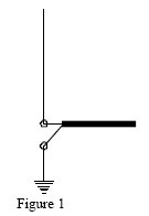
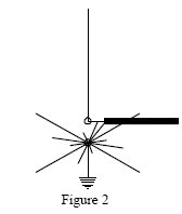
ABOVE GROUND (ELEVATED) INSTALLATIONS (rooftop, tower, mast. etc.)
The problem of ground loss resistance may be avoided to some extent by mounting a vertical antenna some distance above the earth over an artificial ground plane consisting of resonant (usually 1/4 8) radial wires. Four resonant radials are considered to provide a very low-loss ground plane system for vertical antennas at base heights of 1/2 8 or more. This arrangement contrasts favourably with the more than 100 radials for zero ohms loss resistance at ground level, and since 1/2 8 is only about thirty-five feet at 20 meters, very worthwhile improvement in vertical antenna performance can be realized, at least on the higher bands, with moderate pole or tower heights. At base heights below 1/2 8 more than four radials will be required to provide a ground plane of significantly greater conductivity than the lossy earth immediately below the antenna: even so, a slightly elevated vertical with relatively few radials may be more effective than a ground-level vertical operating over a larger number of radials if only because the former is apt to be more in the clear. Resonant radial lengths for any band may be calculated from the formula.