Common-Mode Choke Impedance
The following was produced by Steve Hunt G3TXQ (SK).
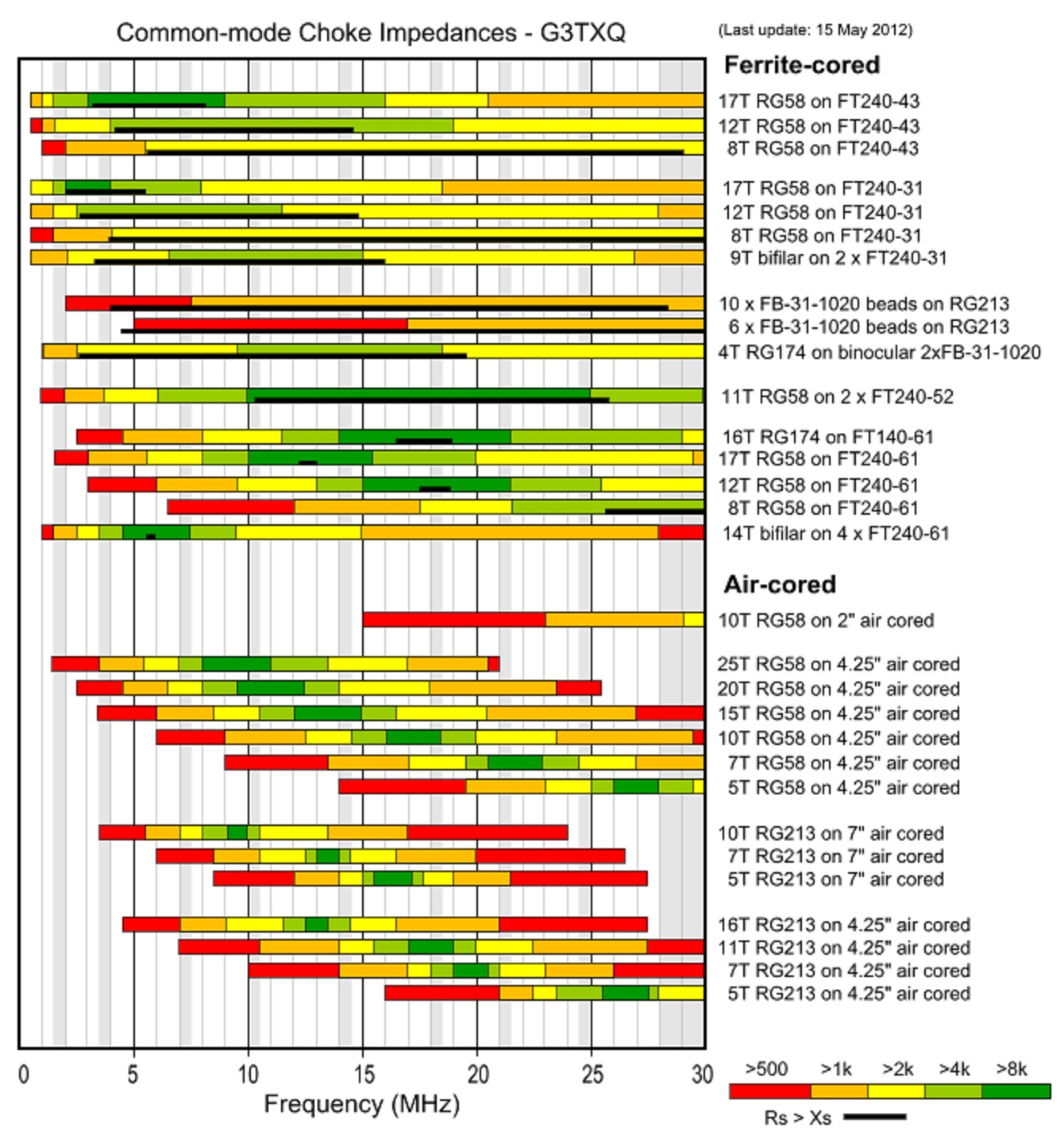
The following chart presents the results of impedance measurements made on a variety of common-mode choke implementations across the frequency range 1MHz to 30MHz. Amateur frequency allocations are indicated approximately by the vertical grey bands.
The colours of the bars indicate the magnitude of the CM (common-mode) impedance; however, depending on the style of choke and the type of ferrite material used for the core, that impedance might be mostly Resistive, mostly Reactive, or somewhere in between. The black bars at the bottom of the coloured bars indicate the range of frequencies over which the choke impedance is predominantly Resistive - that is Rs>|Xs|. No black bars are shown for the air-cored chokes because their impedance is almost entirely Reactive apart from a very small band of frequencies around resonance.
Reactive chokes have the disadvantage that they can "resonate" with a CM impedance path that is also reactive but of opposite sign - in some cases actually increasing the CM current flow rather than choking it; see the section at the bottom of this page for a detailed explanation. Resistive chokes have the disadvantage that if they have insufficient impedance to reduce the CM current to a very low value, there may be significant core heating.
Aim to choose a choke which has a high impedance and is Resistive over the frequency range of interest. For high power applications RG400 coax can be used in place of RG58 with little change to the choke impedances.