Radio Experimenter Theory Notes
|
VHF Transmitter
The VHF transmitter usually consists of a VFO running at around 6MHz. This is
because it is not usual to have an oscillator running at high frequencies such
as 144 MHz. The VFO is multiplied by three multiplier stages. The buffer
amplifier is used following the multiplier stages to avoid the possibility of
the PA stage interfering with the previous stages. The PA delivers the final
output to the antenna.
HF TransmitterThe basis of a typical HF transmitter is a VFO running at 1.75 MHz - 2 MHz. This is because the HF bands with the exception of the WARC bands are all harmonically related, i.e., 21 MHz band = 1.750 - 1.782 x 12. This VFO will be followed by one or more stages of frequency multiplicatioin which will be selected by a front panel switch when you change bend. This combination of the VFO and the frequency multiplier stages is known as the exciter. This is used to dribe the power amplifier which in turn delivers the final output to the antenna. NOTE: Most modern transmitters use frequency synthesisers instead of the VFO. Oscillators
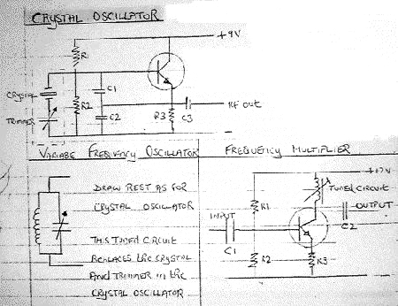
Basically, there are two types of oscillators, the bariable frequency
oscillator and the crystal oscillator. The crystal oscillator is the most
stable but the disadvantage is that it usually operates on a single frequency
or in a VXO in a very narrow band of frequencies, typically around 50 kHz
whereas the VFO operates in a much wider band and thus is the more useful of
the two.
The most critical requirement in an oscillator is the stability. If an oscillator is not stable, the final output frequency will bary (drift) and this may be quite severe, particularly if frequency multiplication is being used. For example, on the 28 MHz band the typical VFO is being multiplied by 16 times, so any instability is also multiplied by a factor of 16.
PRECAUTIONS IN CONSTRUCTION:
Frequency Multipliers
These are usually low power stages running in class C in order to produce a
signal rich in harmonics. The multiplication is usually between 2 and 4. The
output is coupled to the following sytage by a small capacitor. It is most
important that unwanted frequencies produced in the multiplication stages do
not reach the PA stage as they may be radiated and cause interference.
|