
Radio Experimenter Theory Notes
Amplitude Modulation (AM)It is not possible to directly transmit audio into the aether. Firstly audio frequencies are in the range of about 20 Hz to 20 kHz. If we were to transmit at these frequencies, enormous antennas would be required. Secondly, as everyone can hear at the same frequencies, this would effectively leave us with one radio channel on which to transmit. Not very practical. It is of course possible to transmit signals efficiently at far higher frequencies (these are the frequencies to the order of 100 kHz and above). Of course, it's not possible to hear at these signals, but we can effecively encode or superimpose an audio signal on a much higher (radio) frequency signal (hence the term carrier). This is done using the process of modulation. The original way in which voice was transmitted via radio was done by varying the amplitude of the carrier in sympathy with the voice signal (hence the term amplitude modulation). AM modulation consists of a carrier and an upper and lower sideband. To modulate an AM carrier at 100%, you need an audio signal equal to 50% of the unmodulated carrier. This is generally supplied by a high power audio stage using a modulation transformer. The bandwidth occupied is equal to twice the highest modulating frequency, i.e., if the highest audio frequency is 5 kHz, then the bandwidth is 10 kHz. Any attempt to transmit high quality audio would obviously occupy about 30 kHz which is unacceptable in the amateur radio bands.
| Amplitude Modulation (AM) | Frequency Modulation (FM) | Single Sideband (SSB) | |
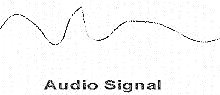 Fig. 1 represents the waveform of an audio signal. Its frequency varies
representing the varying pitch of an audio signal (such as voice) and it's
amplitude varies representing the loudness of the audio signal. A single
constant note from a musical instrument would produce a repetitive pattern, but
voice or music produces a very complex waveform.
Fig. 1 represents the waveform of an audio signal. Its frequency varies
representing the varying pitch of an audio signal (such as voice) and it's
amplitude varies representing the loudness of the audio signal. A single
constant note from a musical instrument would produce a repetitive pattern, but
voice or music produces a very complex waveform.
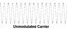 Fig. 2 represents an unmodulated radio carrier which operates at a much higher
radio frequency or RF. When unmodulated, it produces a pure sine wave which
varies in neither amplitude nor
frequency. It must be noted that the diagram represents a radio frequency
signal but is not true to scale. If we looked at an audio frequency signal on
an
oscilliscope which is set at a range where we could see the changes in
frequency or amplitude, the radio frequency would look like a solid bar at the
same scale as the peaks and troughs would be extremly close together at the
same range.
Fig. 2 represents an unmodulated radio carrier which operates at a much higher
radio frequency or RF. When unmodulated, it produces a pure sine wave which
varies in neither amplitude nor
frequency. It must be noted that the diagram represents a radio frequency
signal but is not true to scale. If we looked at an audio frequency signal on
an
oscilliscope which is set at a range where we could see the changes in
frequency or amplitude, the radio frequency would look like a solid bar at the
same scale as the peaks and troughs would be extremly close together at the
same range.
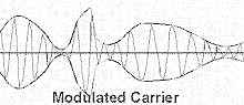 Now, using some circuitry, the audio signal is superimposed upon the carrier to
effectively change it's amplitude in sympathy with the modulating audio signal.
This produces an envelope around the carrier which can be 'detected' on the
receiving side and converted back to audio to be amplified using a conventional
audio amplifier for reproduction in a loudspeaker. The frequency of the
carrier remains the same at all times. It's amplitude is varied and it is the
frequency of the variations in amplitude which represent the audio frequency.
Now, using some circuitry, the audio signal is superimposed upon the carrier to
effectively change it's amplitude in sympathy with the modulating audio signal.
This produces an envelope around the carrier which can be 'detected' on the
receiving side and converted back to audio to be amplified using a conventional
audio amplifier for reproduction in a loudspeaker. The frequency of the
carrier remains the same at all times. It's amplitude is varied and it is the
frequency of the variations in amplitude which represent the audio frequency.