DL4YHF's PIC-Keyerlast updated: March 2003. |
|
|
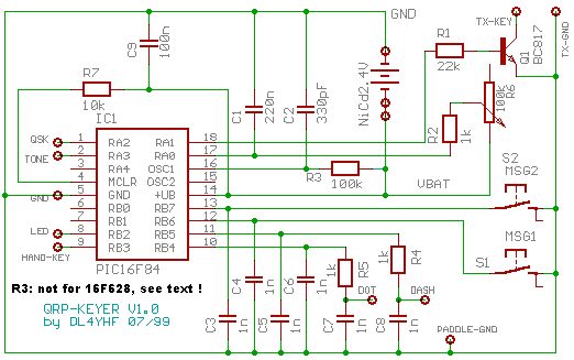
QRP keyer circuit diagram for PIC16F84 (modifications for 16F628 below)
R2, R6 and C1 together form a monoflop for the speed control setting. You may try a different combination of R1, R2 and C1. But don't make R2 less than 1 kOhm, because the keyer programm switches RA0 to GND for a short while to discharge C1 before a poti-reading is started. If you make R2 too low and turn the poti R6 fully clockwise (=max. speed), the maximum current for the output driver inside the PIC may be exceeded. R2 = 1kOhm is a very safe value. R3 and C2 together define the clock frequency of the PIC16F84, which should be about 50kHz. For the PIC16F628, the external RC oscillator is completely different ! The internal clock can be checked on the "OSC2" pin (divided by four). You will only see the clock when the keyer is ACTIVE. There will be no clock signal when the keyer is in sleep mode ( I had to use an RC-oscillator instead of a crysal oscillator, because a low-power crystal oscillator took several seconds to start on wake-up. The first design used a 32kHz-crystal !) C3, C4, C5, C6, C7, C8 and R4, R5 are only needed to block off RF from the CPU. You may leave out C7 and C8, if you don't have too much RF in the shack or use only short leads to connect the paddles. Pins 1,2,5,8 and 9 of the PIC are the "optional" connectors. You may connect a RX/TX switch to the "QSK" output, a piezo speaker to the "TONE" output, an LED with 1kOhm series resistor to the "LED" output if you like. Usually all these "optional" connectors are left unconnected. Sorry but the "Hand-Key"-input does not have a function with the current firmware version. It once was used to connect a "straight" key, but this feature had to be removed because of too little program memory in the PIC and timing problems. You may use this input if you try your own firmware modifications (the source code is available now). R7 may be replaced by a "0 Ohm"-bridge. I only needed this resistor during program development to pull the PIC's reset input low the program crashed. The message buttons S1 and S2 have "normal open" contacts. The pull-up resistors for these switches are inside the PIC (they are software-controllable). If you have trouble with strong RF in the shack, and the keyer starts sending a continuous signal the reason may be the switching transistor (Q1, not the keyer itself). Try two additonal ceramic caps between collector to emitter and base to emitter. These two caps will be included in a future version of the circuit. If the power consumption during standby is higher than 1 microampere (at 2.4 Volts DC in), read the information about the power-down-mode of the PIC.
Modifications of the circuit diagram for a PIC16F628:(revised in July 2004 because the PIC16F628 is now cheaper than the PIC16F84)
|
|
| Back to the Keyer Overview
Translations of the PIC-Keyer into other languages
|
