Diode power meter with 50 Ohm termination for VHF and UHF (144 MHz to 2.4 GHz)

by Wolfgang Buescher, DL4YHF

last updated: January 2023.

This document describes the construction of a very simple diode power meter for low signal levels (between -30 and +20 dBm). It is used in combination with a cheap chinese wideband 'Cavity Coupler' to measure output powers on 2.4 GHz, and reverse power without having to carry around a heavy professional power meter.


Photo of the diode power meter (detector head)
on an SMA Jack Panel Mounting (SMA Flanschbuchse)

The entire 'RF head', including the 50 Ohm termination, is soldered directly on an SMA connector. The terminator consists of two 100 Ohm SMD resistors, directly soldered between the SMA center connector and the ground plate. There are no wires or PCB tracks at all - all components are 'concentrated' around the SMA center pin to minimize lead inductance.


Diode power meter circuit (detector head) V1

There are no active parts on the 'detector head'. To measure signal voltages way below the Schottky diode's forward voltage, the load resistance for the rectified DC voltage must be high. Instead of building yet another microcontroller-based display, I simply use a digital voltmeter with at least 1 MOhm input resistance. Then, with the aid of a 'calibrated' signal source, the detector output voltages were measured for signal levels between -30 and +20 dBm (100 mW is the maximum, limited by the tiny SMD resistors), for 144 MHz, 435 MHz, and 2.4 GHz. The results were entered in a LibreOffice 'Calc' table, and plotted into a LibreOffice X/Y diagram. The X axis is the power in dBm, the Y axis (with logarithmic scale) shows the detector voltage in mV (DC). Note that the 1 pF coupling capacitor, together with the diode's capacitance, will form a capacitive voltage divider - thus your mileage may vary (in contrast to the simplified 'V2' circuit presented later in this document).
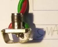
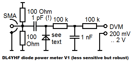
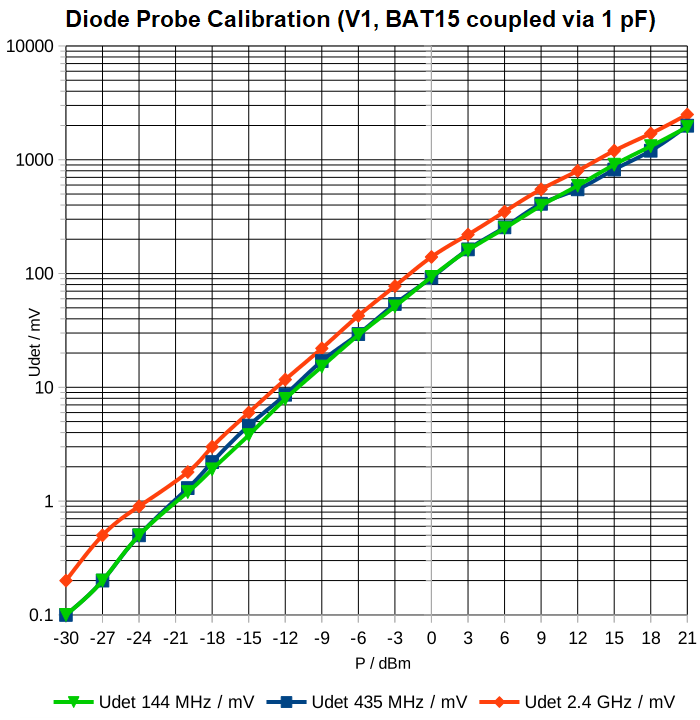
Since the author's last BAT62 decided to drop onto the carpet (where it vanished into dust), an old BAT 45 with up to 1.1 pF at zero bias was used in in the 'V1' circuit shown above. The 1 pF input coupling capacitor (used in 'V1' but not in 'V2') effectively forms a capacitive voltage divider with the diode's junction capacity. Thus, the 'V1' circuit is a bit more robust (because the diode isn't connected directly to the RF source), but less sensitive than in the simplified circuit 'V2' presented further below.
The LibreOffice 'Calc' file for circuit 'V1' can be downloaded from here, so you can replace the measured detector voltages in columns 'Udet 144 MHz', 'Udet 435 MHz', 'Udet 2.4 GHz' (the column titles should speak for themselves). When printed, the entire spreadsheet looks like this (PDF), including the diagram of detector voltage ("Udet" in millivolts) versus RF power (in dBm):


Diode power meter detector curves of the 'V1' circuit, BAT15 coupled via 1 pF
(detector voltage im millivolts versus RF power level in dBm)

When connected to a DC voltmeter and one of those low-cost Chinese directional couplers (used to be available for 6 or 7 Euros in 2020), the detector allows measuring forward- and reverse powers of up to 50 dBm = 100 watts (with a "30 dB" coupler and 20 dBm maximum for the detector itself).


Diode power meter connected to a Chinese directional 'cavity' coupler.
TX output on the left ("IN"), forward power attenuated by 30 dB on top connector.
To measure the reflected power, reverse "IN" and "OUT" port.

For moderate power levels (QO-100 narrow band transponder), a "20 dB" coupler would be better, but it was not available. Anyway, a digital voltmeter in the 200 mV range measures with 0.1 mV resolution, so even with only 1 Watt forward power through the coupler (= +30 dBm), the voltmeter showed 140 mV DC, so the resolution is sufficient to check output power and antenna matching.
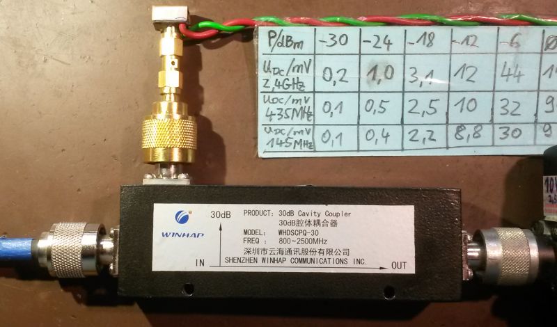
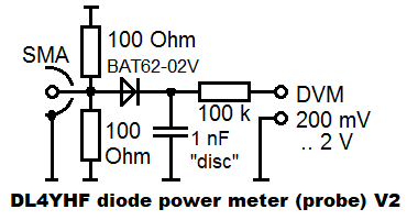
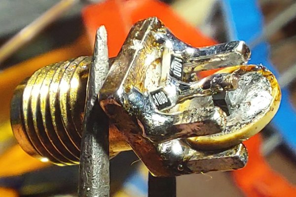
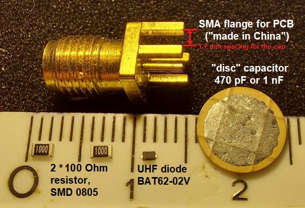
On this occasion: The Chinese directional coupler shown above, with a specified frequency range of 800 to 2500 MHz, can also be used on lower frequencies (with lower coupling of course, but you can take this into account since it's easy to measure). The author's 'WINHAP WHDSCPQ-30' (= coupler with nominal 30 dB 'forward' coupling between 800 and 2500 MHz) delivered on the "30 dB" port...

    +12 dBm "forward" with 50 watts (=+47 dBm) fed to the "IN" port on 435 MHz,
          thus 35 dB "forward" power attenuation on 435 MHz;
    -18 dBm "reverse" with 50 watts (=+47 dBm) fed to the "OUT" port on 435 MHz,
          thus roughly 12 dB - (-18 dB) = 30 dB directivity on 435 MHz;
    +4 dBm "forward" with 50 watts (=+47 dBm) fed to the "IN" port on 144 MHz,
          thus 43 dB "forward" power attenuation on 144 MHz;
    -24 dBm "reverse" with 50 watts (=+47 dBm) fed to the "OUT" port on 144 MHz,
          thus roughly 4 dB - (-24 dB) = 28 dB directivity on 144 MHz;
          not bad if you consider that this is far outside 
          the coupler's specified frequency range.
On 2.4 GHz, the Chinese '8 Watt' WiFi booster delivered a detector voltage of 330 mV "forward" (= ca. +5 dBm on the coupler's "30 dB" output), i.e. approximately 35 dBm = 10^(35/10) mW = 3.16 Watts. This is in the right ballpark for this kind of amplifier when not driven too hard.
With the coupler reversed (3.16 Watts into the "OUT" port, and a questionable 50 Ohm dummyload on the "IN" port), the diode power meter indicated 2 mV "reverse" (= ca. -20 dBm) on the coupler's "30 dB" output. On 2.4 GHz, the "power dummyload" possibly wasn't good enough to check the coupler's directivity (which should have been greater than the measured 25 dB).

Simplified version of the 'detector head' : V2 with BAT62-0V, directly coupled

In January, a second diode power meter was built (V2, with the circuit shown below). This time, with a BAT62-02V diode coupled directly to the 2 * 100 Ohm (in parallel 50 Ohm "dummyload") SMD chip resistors, directly soldered to an SMA flange.


Simplified diode power meter circuit (detector head) V2.
This one delivered about 0.8 mV DC at -30 dBm (!), even at 2.4 GHz.

When connected to a digital voltmeter with 10 MOhm input resistance, the sensitivity was higher, and due to the direct coupling (without a capacitive divider), it is reliable down into the MHz range.
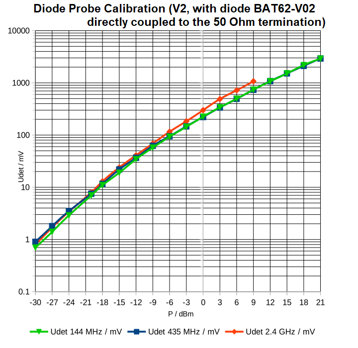
Calibration table for this particular probe (as PDF for printing, and ODS for editing):
Kalibrierung_Diodenmesskopf_BAT63-02V_2023_01.pdf / Kalibrierung_Diodenmesskopf_BAT63-02V_2023_01.ods .


SMA flange with a 50 Ohm "QRP dummyload" and a BAT62-02V rectifier diode.
(Can't spot the diode ? It's between the center pin and the disc capacitor.)


Due to the lack of a 'capacitive voltage divider' between 50 Ohm terminator and diode, V2 is more sensitive, and give reproducable results even if the individual junction capacity ("typical 0.35 pF, maximum 0.6 pF") varies.


Diode power meter detector curves of the 'V2' circuit, BAT62-02V directly coupled
(detector voltage im millivolts versus RF power level in dBm)

The vital parts for the power meter's "detector head" are just the diode, two resistors, a ceramic "disc" capacitor (very important, no leads), and a suitable SMA flange to which the resitors, diode, and capacitor can be soldered directly. Most of them have Teflon dielectric that won't "melt away", especially when soldering the resistors directly onto the SMA flange. Even cheap ones from China were ok:


Vital parts for the diode power meter 'V2', with metric ruler for size comparison.

Note the 1.7 mm spacing between the "ground pins" of the SMA flange, wide enough for the ceramic disc capacitor (with less than 1 mm thickness). The familiar SMA flanges with four ground pins (one in each corner) will work as well, if you carefully remove two of them to give room for the two SMD resistors.

Deriving a formula to convert 'DC millivolt' readings into dBm with a pocket calculator

Having to look up the 'dBm' (decibel over milliwatt) from a table, or a half-logarithmic diagram as shown above in this document is ok, and for many applications, sufficiently accurate.
But a simple numeric expression to directly convert the measured DC voltage into RF milliwatts, or dBm, would be handy. If we had an ideal diode, this would be trivial because

   P = U_rms^2 / R               (P = power in Watts, U_rms in Volts),
   U_rms = U_peak / sqrt(2)      (U_peak = peak voltage in Volts)
   P_dBm = 10 * log( P / 1mW )   (P_dBm = power level in dBm, i.e. referenced to 1 mW)
Try this with the "-20 dBm" (= 0.01 mW) reading at 2.4 GHz with the 'V2' circuit: The DC voltmeter reading was 8 mV. Thus (if the BAT62-02V was an ideal diode), the measured 'rectified' voltage would be equal to the sinewave's peak voltage U_peak, because our digital voltmeter with R_in = 10 MOhm is no significant load for the rectifier.
But at 0.01 mW = -20 dBm, an ideal diode rectifier (or "peak voltage detector") would deliver sqrt( 0.01 mW * 50 Ohm ) = 22.3 mV; that's much more than the 8 mV DC measured with a BAT62-02V.
Obviously (but as expected), at these low voltages, even a 'low barrier Schottky diode' like the BAT62 is not an 'ideal' diode. A formula to convert directly from "measured DC millivolts" into "RF milliwatts" or dBm can only be derived from the 'calibration points' shown in the tables above (0.8 to 1073 mV DC between -30 and +20 dBm).
At the time of this writing (January 2023), the author had tried a few online curve-fitting utilities to derive a simple formula (suitable for pocket caluclators), but the results were neither simple nor accurate. Experiments with 'interactive curve-fitting' are still in an early stage of development ... to be continued...

back to DL4YHF's main ham radio homepage