 |
Small Duoband-Antenna for 2 m and 70 cm by DK7ZB
|
|
|
Small Duoband-Antenna for 2 m and 70 cm by DK7ZB
|
|
Sometimes a small two-band directional antenna is the first choice
for portable operation or for the balcony under restricted
conditions. It is not always possible to accommodate a larger
directional antenna. Especially with vertical polarization, the
space requirement is small and there may still be an installation
option within an existing antenna system. I think with the
dimensions presented here, it is certainly the smallest directional
antenna for the two amateur bands described so far.
Physical
basics |
|
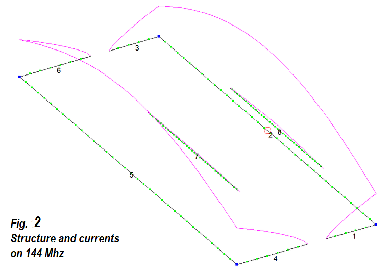
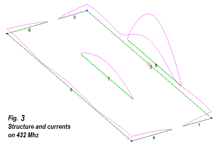
The 2-m-Moxon basic structure also has a 3/2-lambda resonance at 70 cm. However, there are three forward lobes that can be bundled into a single lobe when an open-sleeve element is skillfully positioned for 432 MHz. Figure 2 shows the currents when excited at 144.3 MHz, as expected, hardly anything is induced in the 70 cm elements. It looks different at 432 Mhz (picture 3). It can be seen here that the two outer current maxima on the 2 m radiator (wires 1, 2, 3) are suppressed quite well and the current maximum occurs on the open-sleeve element 8. The numbering of the individual sections is referred to in EZNEC as "Wires", this is also indicated in the dimensions.
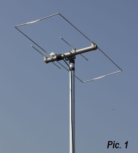
First
of all, I tried to move the 70 cm open-sleeve element inside, which
functions as a virtual radiator. This would not have to prolong the
boom. Unfortunately the result was not as good as the expectations,
which is why this element was installed in the beam direction in
front of the Moxon frame. An additional parasitic reflector brings
more gain and a better f/b ratio.
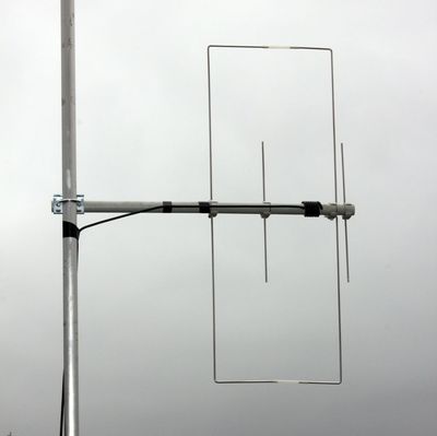
Mechanical realization |
 |
It is important that the length and distance information according
to Tables 1 and 2 refer to the middle of the elements. If you
deviate from this, the antenna is quickly up to 1 Mhz away.
With a 25 mm PVC installation pipe and the appropriate clamps, a
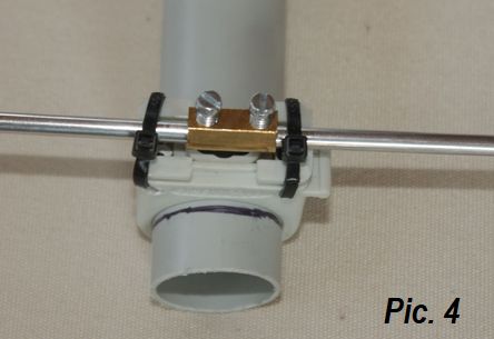
very light and dismantable construction can be created. Since the reflector length is longer than 1 m, I solved the problem by connecting two halves with a luster terminal. This method is shown in Figure 4. Luster terminals are also available for fastening the rods in the feeding point. For this purpose, the radiator pieces are bent inwards at right angles. The coaxial cable is attached directly without a socket and is wound up into a feeding choke as in Figure 5. |
|
In order to give the frame the necessary rigidity, I pushed plastic
tubes onto the ends of the elements. If the antenna is used for
permanent outdoor installation, the feed point must be installed in
a box or protected with hot glue. |
 |
 |
 |
 |
 |
|
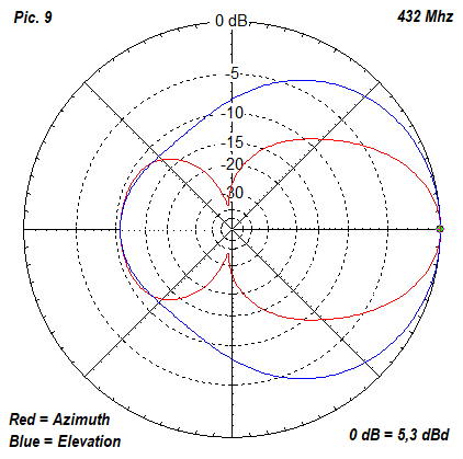
The extremely high
f/b ratio of the Moxon antenna at 2 m is always astonishing.
A beacon signal of S9 almost disappears when the
antenna is turned 180 °. With the data shown,
operation is not only possible in the SSB / CW areas of both
bands. Vertical mounting for FM operation is
also an option and can be used for this antenna.
In this case, the opening angles are extremely large
(141 ° and 114 °) and the bandwidth is fully sufficient for both
frequency ranges.
|
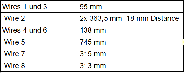
|
Table 1: Lengths of the Elements
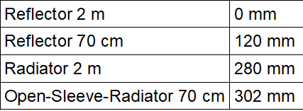
|
Table 2: Positions of the Elements
|
| Sources: [1] Maguire, D. (AC6LA): Antenna modeling Software, download here www.qsl.net/ac6la/ [4] Steyer, M. (DK7ZB): Der Zweielement-Moxon-Beam, FUNKAMATEUR 58 (2009), Heft 3 S. 284
|