The DK7ZB-5-Band-Quad The DK7ZB-3-Band-Quad Oblong+Rhombus The Extended Oblong Delta-Loops

The 50-Ohm-Oblong and Rhombic Loops for the Shortwave Bands

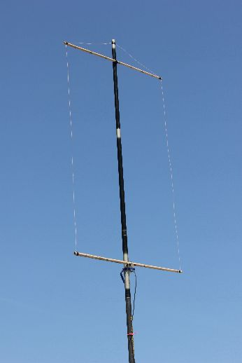
The Picture 1 left shows the classic Quad-Element. The circumference is about 1 lambda, the side-lengths are 0,25 λ. For horizontal polarisation the Quad is fed in the part 1 or 3. The currents show maxima in this two parts. For the impedance and the radiation patterns the two different Quads (Quad-shape and Diamond-shape) show the same data!

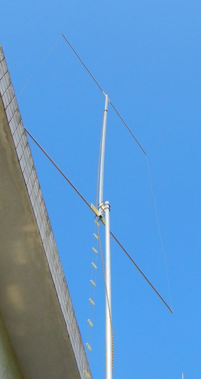
The gain is 1,1-1,2 dBd and the feedpoint impedance 130 +/- j 0 .

The Quad is a stacked system, but for higher gain the two stacked parts 1 and 3 are to close together.

But how we can increase the gain? Let as take a look on Picture 2 ! The distance between 3 and 4 increased from 0,25 to 0,4 λ. By comparing the patterns we see where the gain of 2,6 dBd is coming from.

The data of rectangular loops with different lengths for the vertical and horizontal parts:


The Oblong for 14 MHz with a feedpoint impedance

 of 48 and a gain of 2,5 dBd

The Aluminium tube must be interrupted in the middle part for the feeding. With a wire for part 5 the losses are greater. As monoband antenna you can feed this with a quarterwave-coax-choke. Better is the feeding with a twin-wire as Wireman-cable and an antenna tuner.

The antenna can be used for the 17-m-Band as an extended Oblong with very good DX-results, 30 m is possible, too.

As supporting structure you can use a flag pole or a glass fibre mast, but a metal support is possible. Mount the antenna as high as possible for a low vertical radiation angle.

For other bands use the data in the table above.

The SWR of the 50-Ω-Oblong for 50 MHz shown in the picture below. The Oblong was built with bamboo spreaders and a fishing rod. It was the test-version in IS0 in June 2012. ODX was PY with 80 wtts!

The 50-Mhz-50-Ohm-Oblong at  EA8/DK7ZB

In July/August 2013 I was in EA8 and I had no antenna for 50 MHz. Because I saw a lot of 50-MHz-spots in the cluster I tried this quick and simple solution.

Two PVC-cable-channels I found in the neighbourhood were used as the horizontal spreaders. The feeding choke was made with 8 turns of the RG58-coax around the fishing rod.

The antenna worked quite well, ODX was to OH7UE:   IL27FS <> KP32DM with 5087 km.


Left:

The 10-m-

50--

Oblong

Built by

Dimitri,

SV2YC

More pictures:

SV2YC

The 6-m-50--Oblong by IS0/DK7ZB


The Oblong built by Vladimir, PY2ALR


The circumference of his Oblong is 17,82 m

Vertical side = 5,95 m

Horizontal side = 2,96 m


With a homemade feederline and a tuner he is working all bands from 10-40 m!

The 200-Watt-current-balun with FT140-43

The 1-KW-current-balun with FT240-43 and 2x3 turns 

of Aircell-5 Coax-cable


Rhombic Loops for the Shortwave bands

With the given angles in the scheme below you can get a feedpoint impedance of 50 Ω and a liitle bit more gain as with the diamond square loop. On the other hand the bandwidth is smaller than the Quad loop with 130 Ω.

The data for rhombic loops with 2-mm-not insulated wires. If you use insulated wires, they must be 1,5-2% shorter. No problem, cut the length for best SWR!

The SWR of the 10-m-Rhombus

The Double-Rhombus with two frames in parallel

DXpedition Ascension Island

ZD8D

 in Feb./March 2015

Antenna built by Werner, DJ9KH