Power saving frequency counter for portable radio transceiver. by Robert Tyrakowski, DK7NT
Mai 2001Introduction
Recently there are some new designs of portable HAM-Radio transceivers as replacements of the known and proven IC202 and FT290 as control transceiver for UHF , VHF and SHF transverters have been introduced. However, because they do not employ DDS technology, an important disadvantage of that solution is a rather poor setup and display of the tuning frequency.
Some tried to use conventional frequency read-out units, but these units are not quite accepted due to power consumption and size.Basically the principle of this design is nothing more than a repetition of the already known frequency counter technique. The difference however is , that the realization uses new and modern components.
Because of that, there are new problems for home brewers. Like device acquisition, handling, soldering and programming of the devices. But these remarks should not be a warning, they should be a hint about the challenge to realize it.
Concept and components
The counter consists of already known parts like Input-Unit, Gate, Counter, Display- and Control-Unit. For these units one reqirement was, that the smallest possible number of devices should be used as well as only very low power consumption units. Due to flexibility, a microcontroller should be the heart of the fx-Gnome. Refer to Fig.1 for the block diagram.
Two components are the kernel of the counter. One is the 8051 derivative by ATMEL AT89C4051 [3] , the other is a FPGA by XILINX [2] XCR3128XL. The micro controls all components , the FPGA contains all complex logic of the counter. Only a power supply, an input frequency level shifter , a prescaler and a LCD unit must be connected externally.
The LCD-Unit can be a 3 line , extremely power saving device called "Chip on Glass Display" unit (EA7123), a very small 2 line display (TTR6030) [6] or a standard LCD unit controlled by a bus-translator board. All LCD units are connected via the I2C-Bus.
The prescaler by Motorola [4] is also a very low power unit in a SO8 case. For 1.1GHz only 4 mA current is needed.
Fig. 1: Block diagram of the Fx-Gnome
Features
With regard to the use of that unit in portable HAM Radio equipment, not only low current was important. For receive and transmit a frequency offset can either be added or subtracted (maybe different for TX and RX) . Any prescaller (must not be the embedded one) can also be adapted. 4 different frequency pairs can be selected for read-out. Without a prescaller the counter limit is about 180 MHz. There are 2 different gate times available. (1 sec and 0.1 sec) . This allows a frequency display of 1 Hz or 10 Hz . Of course, the resolution decreases with the divider factor. The known flicker of the last digit is prevented by software.
As already known, a frequency counter is only as good as its time reference. A good compromise is a TCXO of cellular phones . These TCXOs are rather easy to get, they can be adjusted and they are rather unsensitive against temperature variation. The fx-Gnome supports 4 different TCXO frequencies at the moment. A good source can be found here [5] .
To save an additional crystal for the microcontroller , the TCXO frequency is divided by 3 for system clock. It does no matter that the clock is between 3 and 5 MHz depending on the TCXO.Modes
There are three different modes, which can be selected by the apprpriate PC-Tool. The most important difference is a different display , all other functions remain.
Mode 0 : Frequency counter with on-board prescaller: (1)
Value in the PC-Tool : 0
Two external jumpers ( IN6,IN7) allow to select divider factors of 1,2,4 or 8.
The on-board prescaler will be automatically set to the right multiplier factor without
using the PC-Tool.
Mode 2 : Frequency readout with on-board prescaller: (1)
Value in the PC-Tool : 255
Two external jumpers ( IN6,IN7) allow to select divider factors of 1,2,4 or 8.
The on-board prescaller will be automatically set to the right setup without
using the PC-Tool.
Mode 3 : Frequency readout with any external prescaller: (1)
Value in the PC-Tool : 1 .. 254
The divider factor for frequency calculation depends only on the the value
in the PC-Tool. It must be the same as the external divider . All values about
1 to 254 are allowed.
(Mode 1 is not available right now).All modes have the following functions in common:
No Flicker Of Last Digit (NFOLD):
There is a SW mechanism to suppress last digit flicker. The mechanism is off, as
long as the difference of two subsequent counter results is more than +/-1 .
If the result is within +/- 1 for some seconds, the mechanism witches
automatically on. If the character * can be seen behind MHz, the mechanism is off. In other case the mechanism is activated. NFOLD can
not be switched off generally.
Automatic Gate Selection (AGS): (1) (2)
This function allows to switch between two gate times automatically,
depending on the stability of the counted frequency. If the gate is 1
second on and the difference of two subsequent counter values is more
than 30 Hz , the counter switches to 0.1 s gate time automatically. As long
as the difference is more than 300 Hz , the gate time remains on 0.1 s. If the
difference is less than 300 Hz for some seconds , gate time changes back
to 1 s. This function can be selected by the GANG jumper
For real divider values find the counter inputs as following:1 Counter input is JP2 pin 1
2..255 Counter input is JP4 pin 1 for the on-board prescaler.
For other external prescaler, connect the countered frequncy to its input.
Additionally one must connect the output ( JP1 pin 2 of internal
prescaller to JP2 pin 1.If one does not need the on-board prescaller, one can either connect pin 7 of the device to GND (only board REV. 1 + 2), or one should not mount it at all. That saves some mA of current.
If other FPGA's than the XILINX devices is used ( e.g. ALTERA EPM7128AETC) , power voltage should not exceede 8 V.
(1)
For fx-Gnome boards revision 1 there are the following restrictions:Mode 0: There are only divider factors 1 and 2 , because there only one input IN6.
The factor of the on-board prescaller must be set by wires. (normally
already done).
Mode 2: There is only divider factor 1 and 2 , because there only input IN6 .
The factor of the on-board prescaller must be set by wires. (normally
already done).
Mode 3: The on-board prescaller can be used as external prescaller. The factor of the on-board prescaller must be set by wires.(1)+(2)
For fx-Gnome boards revision 1 there are the following restrictions:AGS : This function must be selected by a wire directly at the AT89C4051.
Connect pin 8 with pin 10 (GND) .
Stuff to chooseThere are two ways for setting up the fx-Gnome. For static settings a PC-Program Gnomesetup.exe is needed , for dynamic settings simply jumpers or additional switches are necessary.
The user may choose the following dynamic setup by jumper or additional switches:
TCXO Frequency:
11.3 Mhz,12.8 MHz,13.0 MHz and 14.85 MHz.
FS0,FS1,FS2
Gate:
1.s, and 0.1 s. (0.01s possible, but not recommended)
IN0,IN1
RX/TX Display:
One line for Rx/Tx.
RXTX
Offset:
There are 4 offset pairs , selectable via 2 pins.
IN2,IN3
Modulation:
Two bit selection of CW,FM,LSB,USB
IN4,IN5
AGS (automatic Gate selection):
One pin is used for AGS on/off selection.
Onboard Prescaller selection (depending on mode):
2 pins select the on-board prescaller divider factor.
/1 , /2 , /4 , /8PC-Setup Tool "Gnomesetup.exe"
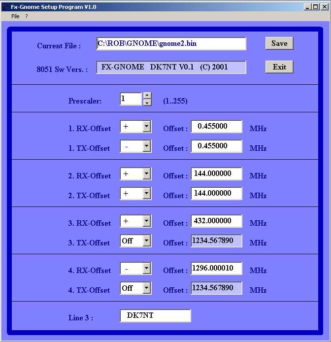
The setup tool is a PC based maintenance tool which can modify the program of the 8051 derivative before programming. That easily allows every user to choose his own offset setup. The micro file must be available in binary form. After modification, the micro can be programmed. Fig.2 shows the desktop view of the tool.
Fig.2: Gnome Setup PC Program
For any offset pair, the user must calculate the appropriate values.The value can be added or subtracted from the counter value, even no offset can be chosen. In this case the displayed frequency is the counter value directly.
If a prescaler is present, also the prescaller factor can also be selected. The counter frequency is then multiplied by the prescaler factor.
The formula is:
Offset = Display frequency +/- ( counter value * prescaller factor) +/- X
X can be any value for any adjustment.
The 3rd line of the display shows any alphanumeric text which can be chosen by the user in the setup tool.
After that , the binary file is ready for programming.
Reproduction
As already mentioned, the compact construction has disadvantages. Normally not all who like to build the counter are able to assemble (solder) the FPGA . The author knows that this limits the number of reproductions extremely. However, if there is enough interest to reproduce the fx-Gnome, the author will help to get the devices , perhaps to get the boards with assembled FPGAs.
[1] DK7NT : http://www.qsl.net/dk7nt
[2] XILINX : http://www.xilinx.com/partinfo/databook.htm#cool
[3] ATMEL : http://www.atmel.com/atmel/products/
[4] MOTOROLA http://search.motorola.com/semiconductors/
[5] TCXOszillatoren ( around DM 15.-) DB6NT http://www.db6nt.com.
[6] Conrad Electronic http://www.conrad.de
