D J 8 W
X
jo43sv Longwave
site
My second and third transmitter
The second:
PSU
I changed the power supply of the first TX some what: The transformer
got a fan and the loading capacitors got in addition a uge Siemens 4700 m F / 400V capacitor.

1000VA, 20-30-40-130-150-170-200V sec.
During test
transmissions with 700W Lf output the transformer got hot, ca. 80 dgr C. I
scraped off all the upper layers of oil paper and fixed a uge fan in front of
it.
Btw. Peter/DF3LP
observed the 136kHz carrier 50Hz modulated. So I built a PSU filter
corresponding to the following diagram by DK7SU and all was fine (Input 80V,
output 71V).


PSU filter - Testversion
The mixer
It is the old mixer out of the first transmitter. The resonance
frequency of the filters have been modified from 136,5kHz to 273kHz fitting the
input of the driver stage.
First circuitry
(accuracy 10exp-5): RF I in: 2448kHz from a YAESU FT1000MP. RF II in: 2175kHz
from a crystal oscillator which is in a 60dgrC HP crystal oven.
Second
circuitry (accuracy 10exp-6): RF I in: 2227kHz from YAESU FT1000MP. RF II in:
2500kHz from TV H-pulse (15625Hz) controlled oscillator.
Power Amplifier (PA). Test version.

It is a mix of the well
known
G0MRF < http://www.g0mrf.freeserve.co.uk/index.htm > and
G3YXM < http://www.picks.force9.co.uk/ >
PAs with some
modifications by DJ8WX. Take the circuit diagram for the Class-D G0MRF
transmitter. The following changes have been made ( addition, change or
elimination of parts) :
1. The very PA with four
IRFP450 MOSFETS is separated totaliter from the driver / push-pull and
protection stage (means two boards, separation between the diodes D4/D5 and the
resistors R20/R21 es between D6/D7 and R39/RV5 /RV4).
The stability resistors
R20, R21, R22 and R23 (all 1W) are soldered directly to the feets of the
MOSFETS.
C22 and C24 decreased to
4.7nF and each has got a 5R in series. C23 has been eliminated.
The switch SW1 has been
eliminated. The number of turns on the secondary of T2 is fixed to 18 (the
power output is regulated by changing the operating voltage). The diameter of
wire for T2 (sec.), L2 and L3 was increased to 1.55mm. T2 is cooled by a fan.
To "tame" the
reactive load (avoid "ringing") a "Zobel network" was
installed, i.e. a 22 Ohm/5Watt in series with a 4,7nF/700VoltAC parallel to the
primary turns of T2. But that is all history. Since I have the possibility to
fine tune the 80m off the shack located aerial matching system remotely, the
"Zobel-network" and one of the fans have been thrown into the junk
box. One has to consider that changing the power output means retuning the
matching system. During TA tests this PA puts some Watt more than 1kW out and
in case some "ringing" occurs I change the tuning of the matching
equipment a little bit and the "ringing" stops. I have to do like
this even if the weather is changing (rain, snow or fog to dry air and vv.).
R25 as part of the over
current protection is like the TX/RX relays RL1/RL2 eliminated.
2. Changes with the push-pull
/ driver / protection stage:
TR1 (keying) with its
surrounding parts are eliminated (the FT1000MP keys the PA and no clicks
detected so far).
The over current
protection (IC5) with its surrounding parts are eliminated (it got on my nerves
during test phase).
C28 (reset time)
increased to 100m F (more time for reaction if the
matching to aerial fails).
R30 (trip point) changed
to 5kOhm potentiometer (for better handling the different power outputs
(20W until 700W).
M1 (SWR meter with
switch) changed to a crosspointer with 10kOhm potentiometer parallel on each
side.
The main changes have
been necessary to run the PA in high power mode. On the way to the final result
p.e. the terminals of the secondary winding T2 desoldered themselves; C22, C23
and C24 es R22 and R23 got hot; the contacts of the relays melted together
during a 1kW output test.
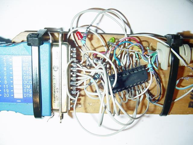
The third:
Forget the analog
exciter (the mixer with its frequency generators): Now, without the PA and its
PSU, it is all digitized. I found the WEB sites of
Murray/ZL1BPU http://www.qsl.net/zl1bpu/
and later on those of Uwe/DK1KQ http://www.mydarc.de/dk1kq/ .
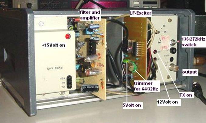
There is nothing left to tell you abt this fine DDS-LF-Exciter. I use the D6b
firmware to get the most out of it: GPS disciplined coherence of the generated
signs and GPS disciplined TX frequency to be prepared for Clicklock QSOs.
I have got one remark:
If you do use a class D push-pull PA you will need 272kHz instead of the 136kHz
output frequency of the LF-Exciter and you will find this frequency at pin 19
(PB7) of the AT90S2313 and it is recommended by the authors to do so. BUT BUT:
I did so and the MOSFETs of the PA exploded using high output power. I
analyzed the spectrum of the driving signal and found the killer
spikes “en masse”. I now use the original output of the
LF-Exciter at TDA7052. In the spectrum one can find a nice 272kHz sine
signal. Filter it out and amplify it and you will have the best driving signal
for a push-pull PA.
What is that?
Manual Keying: Switch the LF-Exciter on in mode M0 (like A0) (HEX: F0, FE0000 nothing
else) and key the PA driver at pins 10 and 8 of the HEF4030 which are connected
via 1kOhm to 12V. Key down means 0V at those pins.
back
to