It all began, when I came back from summer holidays in Denmark last year (2012). On my way home I visited Bent, OZ5ZD in Augustenborg and he showed me his KWM-2, RE with S/N 38057 of about 1971. That had come from the estate of K0ZQD, had been serviced in US and had been working properly. When it was sent over to Denmark it arrived in good order and worked fine, but unexpectedly it soon exhibited some strange behavior. So it was put aside until I got to see it.
This indeed was a strange rig, the calibration oscillator level was much too low and there was practically no peak from the exciter tuning. Even worse, the transceiver was very sensitive to mechanical shock. Even slight tapping would let the S-meter jump up and momentarily increase the speaker output level. I had a feeling that after tapping it would come to life for a short moment, then fall back into agony.
Some tubes had already been exchanged and also new relays K2 and K4 had been installed. No change, so no quick remedy was in sight. I opted to take it home with me and another transport followed. This time first-class, in the back seat of my car.
When I put the KWM-2 on my workbench only a few days later, I had to learn that things had changed again: now the receiver was working properly, the calibrator signal had the right level and exciter tuning was OK. But the mechanical problem persisted, more or less slight tapping anywhere on the chassis would let the S-meter jump up and produce a popping noise in the speaker. While the transceiver was warming up I noticed that I had to tap harder and harder to produce the effect. Would this problem go away by itself without a chance to become identified?
I switched the M-2 off and started thinking all over. Whatever caused the problem, it was somehow influencing the AVC and this was to be seen throughout the receiver circuits. So as a first step I fed the AVC line with a constant voltage. When I switched the transceiver back on, the effect was still there and I still had to tap quite hard to produce it. But now the S-meter did not move any more, as expected. Now I started to isolate the stage in the receiver chain from where the problem was originating. I shorted J22 to ground: gone; grid pin 9 of first mixer V13B to ground: gone; grid pin 1 of RF amplifier V7 to ground: still there. So here was the first result: there was a problem in the circuits between RF amplifier V7 and first mixer V13B.
I hooked up an oscilloscope to V7 pin 5, the anode of the RF amplifier. While tapping the chassis I was able to see a short positive spike, immediately followed by a short negative spike. Countless stories of failing coupling and bypassing capacitors came to my mind, but how could the voltage at pin 5 become more positive at all? The 275 VDC line turned out to be rock-stable and nothing could be seen on V7 pin 6, the RF amplifier's screen grid. When I came that far I really had to tap hard now, so: switch off and again sit down and think.
The spikes at the anode of V7 were short. C272 was ruled out as being too small and shorting of CR5 didn't change anything. Then there was only one further capacitor in the anode circuit: C44 with 1000pF, the coupling capacitor to the grid of driver V8. Was the problem originating from there? But we were on receive and the driver stage was biased off. Yes, biased off, the grid was at about -70 V. When this voltage would disappear by any means, there would be a positive-going spike across C44 and at the anode of V7. I hooked up the oscilloscope to V8 pin2, the driver's grid - and the problem was gone! How come?
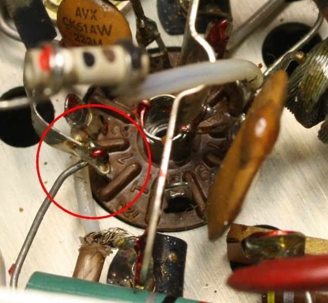
Well, the driver's grid is connected to the tuned circuit around band switch S5 via a short length of shielded wire. The braid is soldered to the shield across the 9-pin socket and the center conductor goes past pin1 to the lug for pin2 (see picture below). A closer inspection of the driver tube socket showed that the center conductor was closely touching the soldering lug for pin1. A little bending of lugs 1 and 2 separated both and the problem was solved permanently.
Now the mechanics of the problem were clear: any contact between pins 1 and 2 of V8 causes a severe de-tuning of the circuit in the anode of V7. That is why the calibrator's signal had been much too low and no peaking had been possible. The driver stage V8 would no longer be off-biased, but that would not be harmful as screen grid voltage for V8 would only be applied in TX mode. The contact between pins 1 and 2 apparently was intermittent, so upon tapping any making or breaking was introducing a large voltage spike into the anode of V7 and at the same time into the grid of first mixer V13B. This signal traveled down the IF chain, produced a large AVC signal and let the S-meter jump up.
Problem solved. And as I did not see any sense in dismantling the connection further for closer inspection, I can only speculate about the root cause. That center conductor must have been close to the lug at pin1 right from production time, maybe there even had been a tiny cut in the insulation. Vibrations and low temperature on the air transport from US to Denmark may have caused something like cold-flow of the insulation: This must have caused an even closer contact until finally an instable electrical contact was established. Tapping the chassis must have broken that contact, restoring proper operation momentarily. Repeated heating of the chassis may have relieved the strain and broken the contact again until only very hard mechanical shock was able to restore it momentarily. So, as I had feared, the problem might have disappeared altogether when the transceiver had been running in a cozy warm shack for some days. But who knows, it might have come back, haunting the operator.
Finally the KWM-2 was taken back to Denmark, this time by train and in an appropriate CC-2 carrying case. And it still works!
This picture shows the space underneath driver tube V8, the circle highlights the place where the inner conductor goes past the lug of pin 1.
to top of page