(2) Put the transceiver flat on the table, then remove the top shield of the PA compartment. You only have to loosen the five screws slightly, the top shield will slide out sideways. Don't touch anything inside yet!
(3) With a suitable metal screwdriver or rod put a short from the outside of the PA cage to the top of the metal strip to which the two plate connectors and chokes are attached. This may sound overly cautious, but remember: Safety First!
(4) Remove the 6146 plate connectors and then remove the two 6146 tubes. Put them in a safe place.
(5) Remove the shield from the 6CL6 tube, then remove the 6CL6 tube and put both in a safe place.
(6) Remove tube V301 on top of the PTO, probably a 6AU6, and put her in a safe place. You may also want to remove V1, a 6AZ8, in order to have better access to the work space. Don't forget to put it in a safe place like the others.
(7) Turn the transceiver over and lay her on her back. Be careful not to trap the plate connectors between table and PA cage.
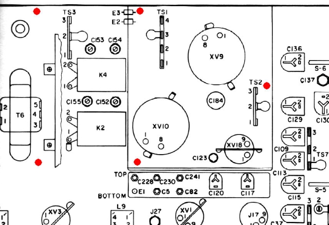
(8) Locate the five screws that hold the PA cage to the chassis. They are roughly there, where the 5 screws are on top of the cage. There is no screw where the cage is flush with the side of the chassis. The following picture shows where these screws can be found.
 (9) Unscrew those five screws and put them aside.
(10) Carefully turn the transceiver over again, then take off the PA cage and put it in a safe place.
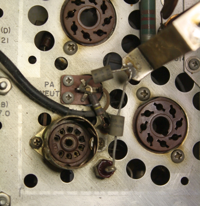
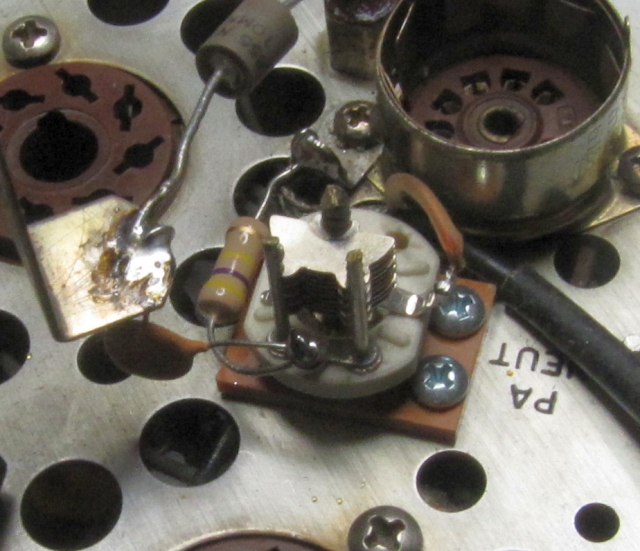
(11) Now, when you look at the space between the PA tube sockets, you will see something like this. And before you do anything else, take a photo to document the situation as it was.
 (12) Unsolder the inner conductor of the small piece of coax cable, the 100K resistor R127, and the 10 pF capacitor C183 from the small neutralizing capacitor C148. Then remove the two screws and capacitor C184. Now it should look like this:
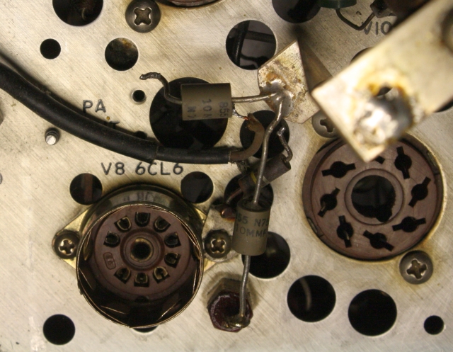 (13) Completely remove resistor R127 and capacitor C183. Proper unsoldering from that metal strip may need quite some heating power. Don't touch the other capacitor.
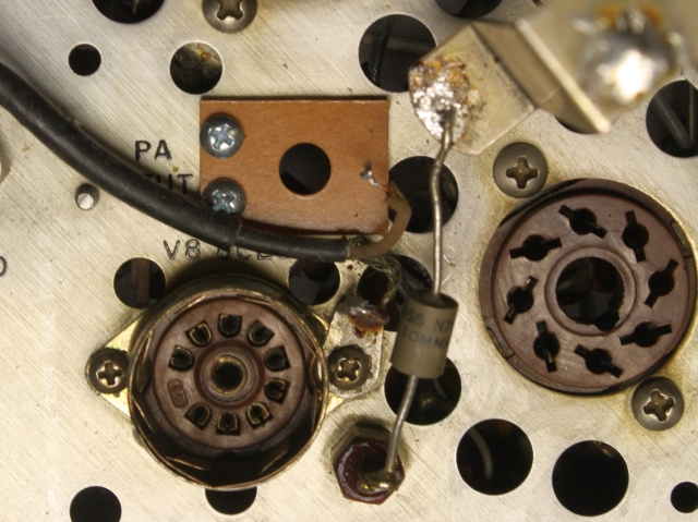
(14) Locate the phenolic mounting board and install it from the top with the two screws supplied where C184 had been. Now the place should look like this:
 (15) Try if you can easily bend the center conductor of the small coax cable to a place right between the two new screws. If you can, then go to (17).
(16) Unscrew the screw that holds the V8 socket and the ground lug. Now you can work at the end of that coax cable. Carefully remove between 1/2 and 1/4 inch of its outer sleeving without cutting into the braid. With a metal pick pry a hole into the braid right where the outer sleeving now ends. Then shift the braid somewhat to loosen it and try to get the inner conductor out of that hole. This way the braid is not cut and still stable and the separate parts at the end of the coax are a bit longer than before. Put the ground lug where it had been and tighten the screw. While you are at it, re-tighten all screws in reach.
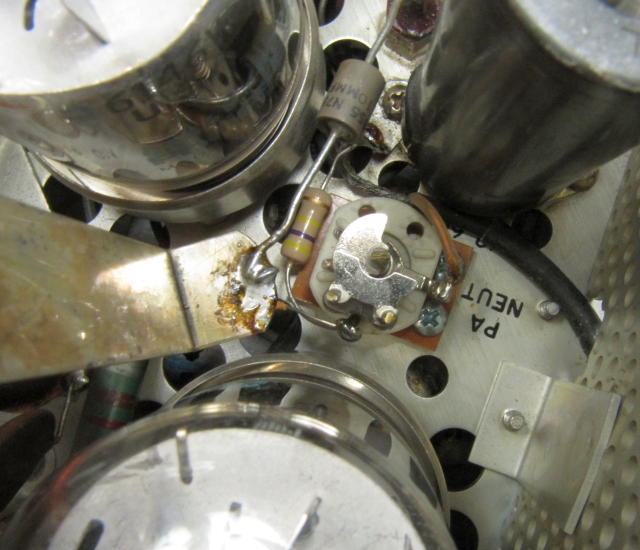
(17) Get the new air variable capacitor and make sure that rotor and stator are fully meshed. Keep it that way as long as you are working at it. Then put it with its shaft downwards into the hole in the phenolic mounting board. Stator and rotor of the new capacitor should be facing up into the PA compartment. The flat sides of the ceramic base should be parallel to the two new screws. Look at the next photo to see the correct orientation. From underneath the chassis install the supplied lock washer and nut and tighten securely while keeping the correct orientation. Check that you did not do anything wrong while tightening that nut in the compartment below the PA tubes.
(18) While dressing and connecting the new parts you should leave enough room for the PA tubes. Their diameter is much larger than that of their sockets! Just to be sure you should get one or both of the 6146 and check the space. Also, the small coax cable should not touch the driver tube or its shield.
(19) Connect and solder the inner conductor of the small coax cable to the solder tab just above the two new screws that hold the phenolic board.
(20) Connect and solder one end of the new .001 2kV disc capacitor C183 to the metal strip, connect the other end to the solder tab on the stator of the new C184. Do not yet solder here.
(21) Connect and solder the new 470K resistor R127 to the ground lug where the coax braid goes, and connect the other end to the solder tab on the C184 stator where the new .001 capacitor is connected. Now solder both connections. The situation should now look like this:
 (22) Double check your work and clean the area. Components should not touch each other.
(23) Re-install the PA cage. There is a wire going to the lower end of the PA choke. Keep that free, don't trap it somewhere. Turn the transceiver over and tighten the five screws that hold the cage.
(24) Turn the transceiver over again and put all tubes back in their sockets. Connect the plate caps to the 6146 tubes and place the shield on the driver tube V8. Don't forget V1 and the PTO tube, in case you followed step (6).
(25) Now, when you look down between the two 6146 tubes, you will see this, your completed work:
 (26) Once again, double check your work, then replace the PA shield cover and tighten the five screws.
(27) Now put the transceiver on one side so you have access to the PA from above and from below. From below, adjust the new air variable capacitor so that rotor and stator are about 1/2 meshed.
(28) Reconnect the power supply cord and connect a dummy load to the antenna jack. It's not a bad idea to connect a loudspeaker, and don't forget to put that VFO plug into J17.
(29) Switch the KWM-2 on, let it warm up and check in RX mode if the calibrator is working. Always watch for smoke!
(30) With MIC GAIN still OFF, switch to TUNE and then to LOCK. Check for proper PA idle current. Increase MIC GAIN and do a quick check for proper drive and output power.
(31) Switch her off again and get that handbook out with the chapter on PA neutralizing. Follow the instructions and make sure you do not use a metal tool to adjust the new C184 neutralizing capacitor from below.
(32) Put the KWM-2 back into the cabinet and finally put all cables and connections back to as they were before you started. Remember, you had taken some photos of that state!