In late spring of 2019 I made contacts with Marcel, EA3IN, in Barcelona. He had a RE KWM-2A that showed very low TX drive and in receive the calibrator signal was 20 dB or more below normal.
We started to discuss the problem via e-mail, but soon decided that the KWM-2A had to travel to Hanover for proper treatment.
Marcel identified a suitable and sturdy transport box and it took only two days until the box was safely delivered by UPS.
The KWM-2A had serial number #38448 and was probably built in early 1972. First inspection confirmed the problem. Then, feeding a 2.25 MHz signal with about 1 mV into J23 delivered a good S9 on the meter. And in TUNE mode with MIC GAIN nearly fully clockwise, a signal with more than 4 Vpp appeared at J23.
This confirmed that the 1st and 2nd IF were more or less working properly. The problem had to be located somewhere around the 2nd mixer V6 and RF amplifier V7, as these stages are operating in both receive and transmit.
Now the KWM-2A had to come out of the box. Tracing the signal with an oscilloscope in TUNE mode showed full signal out of V6 and nearly no signal at the grid of V7. Close visual inspection was not easy in this crowded space, but it became clear that resistor R9 (56 Ohm) at the control grid of V7 was broken, literally exploded. Clearly, this explained the lack of TX drive and RX calibrator signal strength. Temporarily joining the ends with two clips seemed to restore correct operation.
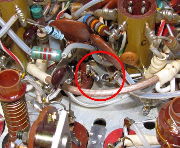
The rest was easy, "only" the two inner RF shields had to come out to give access to R9 (see Fig. 1). The broken resistor was replaced, and now alignment was possible and luckily none of the small ceramic trimmers was "frozen". All functions were to specs.
It remains unclear, why this 1/10 watt resistor exploded. Neither the circuit diagram nor the surrounding parts give any clue for a cause. It can only be speculated that maybe a spurious oscillation led to an overload.
Very soon this no longer "silent" KWM-2A was on its way back home.
|
| Fig. 1 The broken resistor R9 at pin 1 of V7 (RF shields removed) |