
Controlling Icom Radios with LAN or WLAN from Spectrum Lab
Contents
- Remote control via LAN or WLAN
- Pseudo-URLs (as used for remote control in Spectrum Lab)
- Wireless LAN Settings on the RADIO's side (here: IC-705)
- LAN or WLAN connection test (between PC and 'radio')
- LAN or WLAN settings in Spectrum Lab
- Switch to the 'remote' spectrum display in Spectrum Lab
- Audio via Icom's LAN/WLAN UDP 'Audio' port
- Icom LAN/WLAN Troubleshooting
Remote control via LAN or WLAN
More recent Icom radios allow sending / receiving control command, audio, and spectrum data via LAN (e.g. IC-9700) or even Wireless LAN (IC-705), so the days of ever-changing (virtual) "COM port numbers", non-functional USB drivers, are over - at least with these radios.However, configuring the author's IC-705 successfully to make use of all those nice new features was a long journey (which wasn't completely finished at the time of this writing - the audio-via-LAN didn't work properly).
To use Spectrum Lab directly with one of the LAN / WLAN equipped Icom radios, first establish a connection via LAN / WLAN as described below:
In Spectrum Lab's 'Rig Control' / 'TRX Control' panel (explained in chapter 1 of the 'Rig Control' description), enter the device name of the radio in your local network manually into the Field 'Port/Address' on the 'Radio Control' panel.
Since V2.97, this field isn't just a drop-down list for all detected 'COM ports' anymore; instead it's a 'combo box' which also allows typing pseudo-URLs as explained in the next chapters.
For example, with the 'Port/Address' field set to 'udp://IC-705:5001' (without the quotation marks), Spectrum Lab tries to behave like Icom's "RS-BA" software, and appear like a client for the radio's built-in server (using UDP, not TCP/IP); usually with UDP port 50001 for "control", 50002 for "serial", and 50003 for "audio".
IC-705 is the default hostname of -you guessed it- Icom's IC-705.
Pseudo-URLs (as used for remote control in Spectrum Lab)
Pseudo-URLs can be used in various places - not only for remote rig control, but also to specify the transport protocol for certain audio streams. In this case (remotely controlled Icom radios with LAN or WLAN), a Pseudo-URL may be entered in the 'Port/Address' field instead of the old "COM" port number. The parser for that field recognizes if the field contains the name of a "COM port" or a URL-like network resource. Icom radios like the IC-7300, IC-9700, IC-7610 and IC-705 neither support TCP/IP or even HTTP but UDP, thus the pseudo-URL must begin with "udp://" (or "UDP://"; this part of the Pseudo-URL is case-insensitive).For example, the radio's name in your local network is IC-705. Make sure WLAN is enabled in the radio, and check the radio's settings ('Connection Type', 'Connection Settings (Station)', 'Remote Setting' with 'Network Control', etc). For a start, try to use the default UDP port numbers. In that case, the complete string to enter (in Spectrum Lab's 'Port/Address' field) instead of a 'COM port' would be:
udp://IC-705:50001
where "udp://" specifies the transport protocol (User Datagram Protocol), "IC-705" is the radio's name in the network (just by coincidence in this case the name of the radio itself but your mileage may vary), and 50001 is the IC-705's default UDP 'Control Port' number (and again, also here, ymmv).
The next chapter shows where to find / check / modify the connection parameters (including the UDP port number you need to enter as part of the pseudo-URL).
Wireless LAN Settings on the RADIO's side (here: IC-705)
Example configuration in the IC-705 (with firmware version 1.32):Press 'Menu', 'Set', scroll down to 'WLAN Set'. Press 'Remote Settings'.
                 REMOTE SETTINGS          1/2
   Network Control (Valid after Restart)
                                           ON
   Control Port (UDP) (Valid after Restart)
                                        50001
   Serial Port (UDP) (Valid after Restart)
                                        50002
   Audio Port (UDP) (Valid after Restart)
                                        50003  ← These were the default UDP port numbers
                 REMOTE SETTINGS          2/2
   Internet Access Line (Valid after Restart)
                                    ADSL/CATV
   Network User1
                                               ← Tap on this line to open the next screen
   Network User2
              (we'll not use this one for SL)
   Network Radio Name
                                       IC-705
                  NETWORK USER1           1/1
   Network User1 ID
                                         wolf
   Network User1 Password
                                     ********  ← Tap here to edit/display the password.
   Network User1 Administrator                   For this manual, the password was whocares.
                                           NO
LAN or WLAN connection test (between PC and 'radio')
Regardless of the "Connection Type", the WLAN (wireless) or LAN (Ethernet) connection between the radio and your PC (running Spectrum Lab) can be checked the old-fashioned way via the 'ping' command - fortunately, even 'modern' Windows versions still have it, so open a command box (e.g. run "cmd.exe"), then try to "ping" the radio, using its 'Network Name'. An IC-705 showed it somewhere under 'SET' (softkey with 'wrench and screwdriver') .. 'WLAN Set' .. 'Network Name'.- Note:
- IC-705 is only the default Network Name of an IC-705.
You could also access the IC-705 through it's momentarily leased numeric IP address (displayed somewhere in the 'Connection Settings'), but the rig's "Network Radio Name" is easier to use, so we'll use it throughout the rest of this document.
C:\Users\Wolf>ping IC-705


Ping wird ausgeführt für IC-705.local [192.168.178.28] mit 32 Bytes Daten:

Antwort von 192.168.178.28: Bytes=32 Zeit=38ms TTL=128

Antwort von 192.168.178.28: Bytes=32 Zeit=44ms TTL=128

Antwort von 192.168.178.28: Bytes=32 Zeit=48ms TTL=128

Antwort von 192.168.178.28: Bytes=32 Zeit=54ms TTL=128


Ping-Statistik für 192.168.178.28:

   Pakete: Gesendet = 4, Empfangen = 4, Verloren = 0

   (0% Verlust),

Ca. Zeitangaben in Millisek.:

   Minimum = 38ms, Maximum = 54ms, Mittelwert = 46ms


C:\Users\Wolf>
LAN or WLAN settings in Spectrum Lab
From Spectrum Lab's point of view, it's irrelevant if the connection uses a LAN (Ethernet cable) or a WLAN (wireless). All it needs to know is the radio's "address" in the network. The 'ping' test in the previous chapter confirmed that the radio can be addressed via its 'Network Name', e.g. IC-705, so we can copy that name as part of the pseudo-URL (e.g. udp://IC-705:50001 in the screenshot below).The low-level network protocol used in LAN- or WLAN-equipped Icom radios (e.g. IC-7610, IC-9700, IC-705, IC-905) is always UDP (not TCP or even HTTP).
UDP port number 50001 is only the default for what Icom calls 'Control Port' (displayed somewhere under 'WLAN Set' .. 'Remote Settings' in the IC-705, and under 'NETWORK' in the IC-9700).
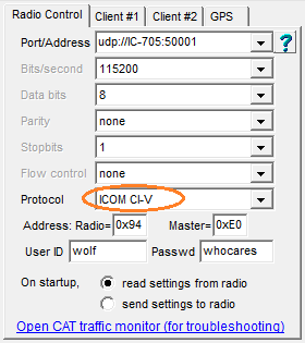
SL Configuration under 'TRX Control' / 'Radio Control'
for an IC-705 remotely controlled via Wireless LAN.
Most of the old 'serial port' parameters are irrelevant here.
'Address: Radio=...' is the radio's "CI-V Address".
Default CI-V Addresses for some Icom radios are listed here.
After filling out the required fields as shown in the above example (or course with your user-ID (aka "user name") and password for the first time, click on the link-like 'Open CAT traffic monitor (for troubleshooting)'. This opens Spectrum Lab's built-in 'CAT traffic monitor' (CAT = historic abbreviation for 'Computer Aided Transceiver / Tuning'), which not only displays the CI-V contents, but also the UDP packets during the log-in phase.
Because the LAN/WLAN support in Spectrum Lab was in an early development phase (at the time of this writing), things may go wrong, UDP packets may not arrive (especially via WLAN or the internet), etc etc. Thus the 'traffic monitor' may help to troubleshoot this.
Switch to the 'remote' spectrum display in Spectrum Lab
When successfully connected to, and logged into to the Icom radio, optionally configure Spectrum Lab's main frequency analyser to show Icom's broadband spectrum instead of the data from Spectrum Lab's internal Fourier Transforms (FFT). Here just repeated in a nutshell:- In SL's main menu, select
Options .. Spectrum display settings, part 2 - In the group box Special display options, check
show REMOTE spectrum (via CI-V) .
- Alternatively (but this will 'undo' many other settings in Spectrum Lab):
In SL's main menu, select
Options .. Other amateur radio modes .. Broadband Spectrum from Icom radios (via CI-V)
If all works as planned, a display like the following should appear:
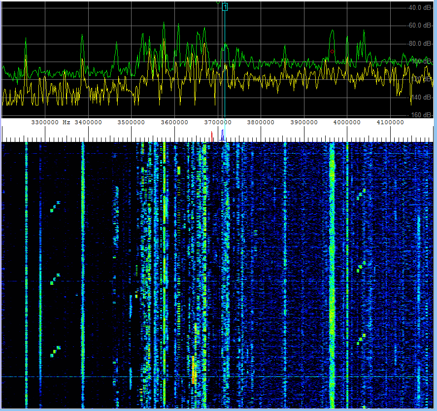
Broadband spectrum (1 MHz wide) read from an Icom radio via CI-V.
Again, details about the remote spectrum display are here.
Audio via Icom's LAN/WLAN UDP 'Audio' port
When trying to receive the audio signal from an IC-705, connected only via WLAN (without 3rd party software in between) nothing seemed to work 'right out of the box'. For that reason, you may be better off with 3rd party software like Icom's 'RS-BA' or wfview (the latter being free and highly recommended if you need low-latency audio).Icom LAN/WLAN Troubleshooting
Especially when used on a Wireless LAN, both the remote spectrum display and the audio stream (received from an IC-705) were unreliable. Thus, the formerly simple 'CAT Traffic Monitor was drilled up into a hypercomplicated beast (that not only lists the high-level CI-V messages, but also the non-CI-V "log-in" procedure in a half-way human-readable format). Specifying all those messages here would be overkill, but there's an example (saved in Rich Text Format because that's what the colourful display uses internall). When running into trouble, the messages in the CAT Traffic Monitor can be exported in that format as described here.For comparisons, an almost complete example with most of the traffic between Spectrum Lab and an IC-705 (except for most of those "PING" and "IDLE" messages being removed automatically, after the first few dozen) has been recorded as described above. It is kept in the Spectrum Lab installation archive in the logfiles subdirectory, in a file named
TrafficLog_Example_IC-705.rtf .
Just a quick run-down of the LAN/WLAN-specific messages contained in the above file:
- TX (lines marked with a yellow background in the RTF)
- "Transmitted"; message from client (e.g. Spectrum Lab) to server (radio).
- RX (lines marked with a cyan background in the RTF)
- "Received" from the client's point of view, i.e. message from server (radio) to client.
- (UDP Ctrl)
- A non-CI-V message on Icom's UDP "Control" port.
If Spectrum Lab's 'Rig Control' parser can make sense out of the data, the machine-generated commend will contain more details like 'Connect from port 53799 to 50001', etc.
(In the sample file linked above, the 'UDP Control' port was 50001 on the server side. On the client side, it's an ever-changing 'ephemeral port', where the actual decimal value (e.g. 53799) has no special meaning. It was just 'free' at the time the Windows Socket Service was asked to send a message - that's all.
- (UDP Serial)
- This is the port over which, AFTER SUCCESSFULLY CONNECTING the radio,
the CI-V messages are exchanged. Because decades ago, CI-V was used
over a single-wire 'serial port', the name was kept even though today
the 'serial port' may actually be USB or this particular UDP port.
- (UDP Audio)
- This is the port over which, AFTER SUCCESSFULLY CONNECTING the radio,
short blocks with audio samples are exchanged.
Only in the initial phase, there are also messages like "are you ready ?" from client to server, and responses like "I-AM-READY" from server to client.
This complexity was one of the 'nice surprises' - even on the "UDP Audio Port", there are not only 'audio' message (blocks of compressed samples) but also certain control messages.
- "Idle"
- Appears to be necessary in both directions (client to server, server to client)
on all ports ("Control", "Serial", "Audio") when there is nothing else to send,
to keep the network traffic up ;o)
- "Ping"
- Necessary (at least on the "Control" port) to detect if the guy
on 'the other end of the line' is still there. This is more or less
a consequency of using UDP (User Datagram Protocol)
instead of TCP (Transmission Control Protocol),
where the network protocol itself will detect if a connection is still intact,
even when there's no payload to send or receive. Thus, even through
from the Internet Protocol's point of view, UDP is a
connection-less protocol, in this case (Icom "RS-BA Protocol"),
client and server actively keep "pinging" each other
to check if the UDP 'connection' still exists.
- All 3 UDP ports 'connected'
- As indicated by the colour-less background, this is not a message on any UDP port,
but an 'info' injected by the Rig Control parser into the logged stream.
The log-in, 'Connect' and 'Are-you-ready' / 'I-am-ready' - back and forth negotiations between client and server seem to have finished, so the 'normal' CI-V parameter polling cycle may start.
Except for the slightly different format of certain CI-V messages when embedded in UDP frames (e.g. the non-fragmented SPECTUM DATTA), there is not much LAN / WLAN specific about this.
- ; CiV-Payload:len |pre| to fm parameters.. postamble=FD
- Comment automatically inserted by the GUI (into the RTF) if the
previous packet was UDP without CI-V,
and the next line only shows CI-V payload
(for clarity, without the UDP overhead).
The line is vertically aligned with anything that follows (until the next "Non-CI-V" datagram).
|pre| = two-byte CI-V "preamble" (FE FE),
to = single-byte CI-V "to"-address (e.g. 0xA4),
fm = single-byte CI-V "from"-address (Icom recommends 0xE0' for the "Controller"),
postamble = the last byte in a frame, when CI-V travelled over a real 'serial port', decades ago.
parameters : This is what you can look up in the particular radio's "CI-V REFERENCE GUIDE". At least, that was the document name for the IC-705.
Last modified : 2023-07-04
Benötigen Sie eine deutsche Übersetzung ? Vielleicht hilft dieser Übersetzer (Google Translate) !
Avez-vous besoin d'une traduction en français ? Peut-être que ce traducteur vous aidera !