By Wolfgang Buescher, DL4YHF
Last modified: December 14, 2015.
Note: Some links only work if this file is located in the help directory of Spectrum Lab.
If so, you can return to the main index here or look
at other sample applications .
The entire document, including the configuration files, is in an early stage of development !
Check for the latest release of Spectrum Lab somewhere at
www.qsl.net/dl4yhf .
Contents
- Introduction
- Stability requirements
- Different 'EbNaut recorder' configurations (*.usr files)
- EbNaut_Rcvr.usr (for real input from a single channel, typically the soundcard)
- Adjusting the audio center frequency
- EbNaut_Rcvr_SDR_IQ.usr (for complex input, e.g. I/Q from direct sampling SDR)
- How to start
- Check frequency and oscillator stability
- Switch back to the EbNaut (radio-)frequency
- Start and stop recording
- Scheduled Audio File Recording
- OT: Sending EbNaut with Spectrum Lab
EbNaut is a coherent BPSK mode, developed by Paul Nicholson. EbNaut is intended for long-range, low-power (by terms of ERP) transmissions
in the VLF range. Details and the EbNaut software are available at abelian.org/ebnaut/.
As described on the website linked above, EbNaut requires precise timing, and a very stable sampling rate
which is beyond the capabilities of a PC's audio input device (soundcard, USB audio dongle, etc). More on that in
the next chapter ('Stability requirements'). The rest of this
article focuses on how to overcome the shortcomings of the PC's audio hardware, by using a GPS receiver to eliminating
the soundcard's sampling rate drift (as far as possible), and how to configure Spectrum Lab for this purpose.
This document is heavily linked to the help system of Spectrum Lab. For a start, don't let those links distract you; they are here to guide you
if more in-depth information is necessary to customize the settings.
The configuration file for the EbNaut receiver is contained in the installer (actually located in ?/configurations/EbNaut_Rcvr.usr).
It can be loaded from the 'file' menu ('load settings from', then find your way to the file), or through the 'quick settings' menu
('Other Amateur Radio modes' .. 'EbNaut Receiver (decimating wave file recorder)'). Please note that the EbNaut decoder
software, developed by Paul Nicholson, should be installed in another directory on the harddisk. The directory where SL stores
the wave file can be customized as explained here.
2. Stability requirements for EbNaut and frequency stabilisation methods
Look at the example presented at abelian.org/ebnaut/notes.shtml :
> A message transmitted on 8822 Hz by Dex McIntyre (W4DEX) in North Carolina :
Message length = 25 characters, Symbol period = 8 seconds, Total message duration = 24320 seconds = approx. 6.75 hours.
As explained at abelian.org/ebnaut/appendix.shtml, chapter 'Timing and Phase Errors',
a reference phase search in steps of 30 degrees incurrs a maximum loss of 0.3 dB. With 30 degree steps, the maximum phase offset (difference)
would be 15 degrees ('true' phase in the center between two steps), so let's try to keep the additional phase error
caused by the A/D converter's sampling rate drift below 15 degrees - keeping in mind that the Ionosphere, the transmitter, and other parts in the receiver
will add more phase errors.
With a maximum acceptable phase error (caused by drifting ADC clock, etc) over the coherent measurement time
of 15 degrees, that's
15° / ( 360° * 8822 Hz ) = 4.72 microseconds during the 6.75 hour transmission,
which requires an oscillator with a relative stability of
4.72 us / 24320 s = 194 * 10^-12 = 0.194 * 10^-9 (= 0.194 ppb, parts per billion),
or a frequency accuracy of 8822 Hz * 0.194 * 10^-9 = 1.7 uHz (for the 8822 Hz carrier).
Similar example, from an experiment on LF (137.780 kHz), 9 characters, 704 symbols, 0.5 seconds per symbol -> 352 seconds total :
15° / ( 360° * 138 kHz ) = 0.3 microseconds during the 352-seconds transmission,
which requires an oscillator with a relative stability of
0.3 us / 352 s = 852 * 10^-12 = 0.852 ppb,
or a frequency accuracy of approx. 138 kHz * 0.852 * 10^-9 = 117 uHz (for the 138 kHz carrier).
That's tough, even for an OCXO.
A good free-running OCXO drifts by less than +/- 2 ppb per day (by ageing), thus for long / slow EbNaut messages, additional stabilisation
is desirable. Fortunately, low cost GPS receivers with a pulse-per-second 'sync' output are available.
In Spectrum Lab, such a GPS receiver can be used to monitor the soundcard's sampling rate drift, and also provide the GPS-based
timestamps for the EbNaut decoder. Details about interfacing a GPS receiver to the soundcard are in the Spectrum Lab manual.
Other possibilities (which have not been tested by the author of this document yet) :
- feed a frequency-divided signal from an OCXO, GPSDO (GPS-disciplined oscillator), or similar into the soundcard;
and let SL use this as a 'reference frequency' to measure / compensate soundcard oscillator drift;
- use a synchronized analog/digital converter hardware (some "studio-grade" recording equipment supports
external synchronisation, but this method also has not been tested yet).
- build your own A/D converter hardware clocked by an OCXO (etc, see above), for example this one
(which can easily be interfaced to SL ..); or a similar PIC-based ADC (but you will possibly need extra software for that).
- Modify the oscillator in your SDR (FiFi, SDR-IQ, Perseus, etc) to improve its stability.
This may be easier than trying to frequency-lock the soundcard's oscillator plus the oscillator in your HF receiver,
especially if the oscillators in double- or triple conversion superhets are not synchronized (clocked by the same reference).
At least in the SDR-IQ and Perseus, all clocks which affect the 'VFO' and the IF (output) sampling rate are derived
from the same source (which are 66.666.. MHz and 80.0 MHZ, respectively).
For direct sampling SDRs like SDR-IQ or Perseus (but not the 'FiFi'-SDR),
there is only one oscillator to lock.
The FiFi-SDR has a programmable synthesizer and a separate oscillator for the internal soundcard, making it more difficult to stabilize.
For some transceivers (like the IC-706), there is only one oscillator from which all other clocks
are derived. In the author's IC-706, it's a 30.0 MHz oscillator which can easily be locked to 10 MHz - and without that, it's not
suitable for this application because the IC-706's oscillator (non-TCXO) drifts too fast, and 'too far' to be compensated
via software even at 137 kHz.
Radios with a more exotic oscillator frequency may be lockable with a synthesizer-based frequency reference like the 'XRef' by VK3HZ.
For many other classic amateur radio rigs (unfortunately, including the Kenwood TS-850 and many radios
of that era), there are multiple independent oscillators affecting the output 'audio' frequency,
making it difficult to stabilize. In that case, consider a simple homebrew receiver with a 'fixed frequency' oscillator
for the downconverter. All it needs to do is mix the 'radio frequency' down to a frequency which can be processed
with your PC's soundcard or similar device. It doesn't even need to be an receiver with I/Q output. See the notes on avoiding
1/f ("low frequency") noise in one of the following chapters.
3. Description of the 'EbNaut recorder' configurations
Depending on the receiver type (SDR with I+Q output, direct reception via soundcard, or external receiver
with normal audio output), one of the configuration files explained further below can be used.
These configurations will be contained in the SL installer or zipped archiv in the next release,
or can be downloaded from here (possibly more up-to-date than the files
contained in the SL installer). SL versions prior to V2.90 lack the possibility
to tap the input for the 'audio recorder' at the decimated input for the main frequency analyser.
They had to use either the decimator at the input of the processing chain ('preprocessor' between L0/R0 and L1/R1),
or the decimating option in the audio recorder.
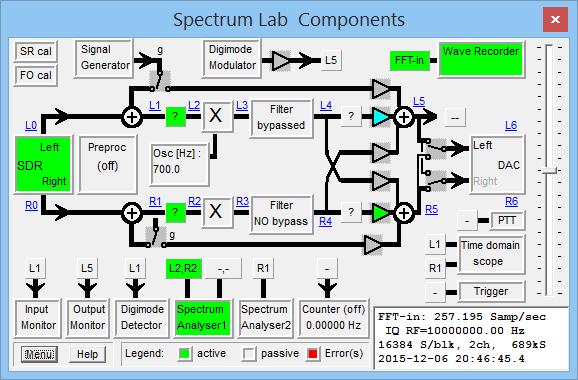
Screenshot of the signal processing chain,
here using an SDR-IQ with stabilized oscillator for input.
The input for the main spectrum analyser is tapped after the first set of 'DSP blackboxes'
(boxes labelled ' ? '), which are configured as noise blankers. The noiseblanker settings can be
modified via context menu (click on the box between circuit nodes 'L1' and 'L2').
Not directly shown in the circuit window but essential for this application:
There is a decimator before the input to the FFT ('FFT-in'), which reduces the sampling rate
from e.g. 55 kSamples/second from the SDR-IQ to a few hundred samples per second.
The output from the decimator is not only used to improve the frequency resolution for the
spectrum display (FFT), but -in this configuration- it also feeds the wave recorder.
The properties of the recorded stream can be examined by clicking at the recorder's signal source.
In the screenshot shown above, this is the box showing 'FFT-in' in the upper right corner.
- Note
- If the audio recorder was connected anywhere else (instead of 'FFT-in'), it would record
the entire IF bandwidth, at the sampling rate of the SDR or soundcard,
possibly filling up your entire harddisk during one night of recording !
By using any of the 'EbNaut' configurations presented below, you only record the 'frequency band of interest'.
In the configuration of the screenshot shown above, the SDR provided a precise sampling rate,
so the 'input preprocessor' between L0/R0 and L1/R1 in the circuit is passive.
In other configurations, for example those using a soundcard for input, the preprocessor will be
active (green colour), and resample the signal from the 'measured' sampling rate to the 'nominal'
sampling rate.
3.1 EbNaut_Rcvr.usr (for real input from a single channel)
Use this file for VLF with the soundcard, or for LF with a suitably stable receiver (SL cannot stabilize the drifting oscillator in the radio yet,
it can only compensate the drifting sample rate in the soundcard).
In EbNaut_Rcvr.usr (configuration file for Spectrum Lab as EbNaut receiver / recorder but not a demodulator / decoder),
the input is read from the soundcard by default, but the input device can easily be switched to any of the SDRs mentioned above
(details on that here). The input signal first runs through a noise blanker at the highest possible sampling rate.
After that, the signal is multiplied with a complex oscillator, which produces an I/Q signal (aka complex baseband signal),
and decimated to a sampling rate of a few dozen samples per second (depends on the 'observed bandwidth').
The complex, downconverted and decimated I / Q signal feeds the main frequency analyser's FFT, as well as the wave file recoder.
This allows checking the frequency on the spectrogram (which, for EbNaut, is of limited use (*) ).
The main purpose of the downconversion / decimation is to keep the file size in reasonable limits, and since the EbNaut signal
is only a few Hertz wide (or even less, depending on the symbol rate), it would be a waste of disk space to record an entire
96 kHz (or even 192 kHz) wide band.
(*) For EbNaut, the spectrogram is of limited use, because the EbNaut decoder
decodes BPSK signals which are too weak to be visible on a spectrum,
even with a long FFT, i.e. equivalent noise bandwidth in the sub-mHz range.
The original 'radio center frequency' is stored in the header of the wave file (along with the downconverted samples).
For the EbNaut decoding process, it is also important to know the precise time (in UTC) of the first recorded sample.
Because none of these infos can be stored in a 'normal' wave audio file, there is an extra 'info chunk' header written to the file
which any decent audio-analysing software should be able to skip (but we have seen cases where programs rejected wave audio files
due to the presence of 'unknown' chunks in the header). For software developers, the format of this extra header is specified
here.
The 'radio center frequency' stored in the header is the sum of the external receiver's VFO frequency,
aka 'USB dial frequency' in WSPR lingo, plus the HF receiver's audio center frequency (typically 500 ... 2500 Hz).
The default 'audio center frequency' in the EbNaut_Rcvr configuration is 1000 Hz, but this can be modified
as explained in the next paragraph.
On this occasion: If you use an external 'all mode' receiver to receive EbNaut on LF, don't switch it to CW !
Many radios treat CW like "narrow band LSB" (lower side band), and you may end up with the 'wrong sideband'
in your recordings, and some headache to find out the correct frequency to be entered in the EbNaut decoder's
Freq offset field.
If, for some reason, you need a different audio center frequency to suit the output of your LF receiver,
modify the 'Center Frequency' in the FFT configuration. This is actually the frequency of a software NCO, which
translates the real-valued audio signal into a complex baseband signal (with I and Q component), before the decimation:
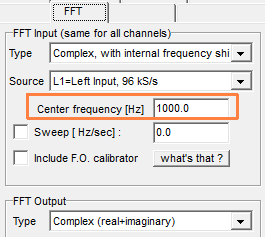
(Screenshot of SL's FFT settings dialog)
Because in the EbNaut configurations, the audio recorder is tapped to the same decimated I/Q signal
for the wave recorder (as explained in another chapter of this document), the modifications described above
will also affect the wave file passed to the EbNaut decoder. The 'radio frequency' saved in the wave file header
is the sum of the 'VFO frequency' of your external receiver, plus the (audio-)'center frequency' of the FFT shown
in the screenshot above.
The frequency scale of SL's main frequency analyser also shows the radio frequency (at least in the EbNaut configuration;
beware that adding the external 'VFO frequency' can be turned off in Spectrum Lab .. details about the
importance of a correct and precise 'VFO frequency' setting in a later chapter.
3.2 EbNaut_Rcvr_SDR_IQ.usr (for complex input, e.g. I/Q from direct sampling SDR)
Use this file along with an SDR-IQ, Perseus,
or similar 'direct sampling' receiver (select your input device here).
On LF (137 kHz), the stock 66.666 MHz oscillator inside the SDR is not stable enough, so you will to stabilize it
by hardware (or, maybe in a future revision of SL, in a 'click-lock' like approach as once used by G3PLX).
Until then, consider locking the SDR's internal clock (which fortunately provides the NCO reference and also the IF (I/Q)
output's sampling rate) as described by G4HUP, or try a low-noise PLL to provide
a 66.666 MHz clock derived from your 10 MHz frequency reference (GPSDO, or maybe a very good free-running OCXO).
As of December 2015, tests are still under way, the author of this file has not successfully received really weak EbNaut
signals on LF but that's due to local QRM... a drifting oscillator seems to be easier to cure !
The configuration is almost the same as in EbNaut_Rcvr.usr. The main difference is here the FFT's input pre-processor uses
I/Q input, directly from the radio (in the EbNaut_Rcvr configuration, the input from the soundcard is multiplied
with an I / Q oscillator in software). In any case, the result (recorded also in a wave file) is always an analytic signal
(with I- and Q-component), decimated with adequate low-pass filtering to a few ten or hundred samples
per second in any case, 'tapped' at the same circuit node as the input for the FFT in SL's frequency analyser.
- Note
- Configurations distributed before December 2015 had the 'Wave Recoder' configured for 16-bit integer samples.
Regardless of your receiver configuration, make sure you change this to '32-bit floating point' under
'Options / Wave File Settings'. The same applies to any other of the 'EbNaut_Rcvr' configuration files !
The same configuration (EbNaut_Rcvr_SDR_IQ.usr) can also be used for similar 'I / Q' sources, including
and external A/D converter hardware. For example, various input sample formats can be 'streamed in' via serial port.
After loading EbNaut_Rcvr_SDR_IQ.usr for the first time, you will need to select the input device anyway.
4. How to start
After loading a suitable configuration, check if the input levels are ok
(more on that here),
and -which is even more important- check the frequency displayed in the spectrum analyser.
This chapter describes a few possibilities, preferrably with an unmodulated reference signal (GPSDO-based),
or (second best) an LF time signal (MSF, DCF77), or (third best) a longwave AM carrier like BBC Radio 4, Droitwich, on 198 kHz.
Other off-air references are listed here.
4.1 Check frequency and oscillator stability
Enter the frequency of 'your' reference in SL's VFO frequency field.
If a remotely controllable receiver is used (or an SDR controlled by SL), the new VFO frequency is also sent
to the radio. Remember to switch back to the EbNaut frequency later.
Wait until a new FFT has been calculated, after changing the VFO (or NCO) frequency.
To get a faster display update for a 'coarse initial check', you can reduce the FFT size, at the expense of frequency resolution:
-
Right-click into the spectrum graph or waterfall display, select 'FFT settings', 'FFT input size'.
With a decimated sampling rate (for the FFT and the wave file) of ~200 Hz,
a 16384-point FFT gives a frequency bin width of 12 mHz, but (with a good SNR) the frequency displayed
in the 'Cursor' panel provides a better resolution as explained here.
After a few minutes, you can read out the precise frequency by pointing at the peak in the spectrum.
If the coarse check was ok, test again with a longer FFT window, for example (copied from the 'FFT properties' description):
Effect of FFT settings with fs= 257.195 Hz:  (*)
Width of one FFT-bin: 490.560 uHz
Equiv. noise bandwidth: 735.839 uHz
Max freq range: -54.2986 Hz .. 74.2986 Hz
FFT window time (length): 33.97 min
FFT window overlap: 75.0 % (automatic) |
(*) This is the decimated sampling rate, entering the FFT in the time domain.
The 34 minute FFT window gives a 1 / (34 * 60 seconds) = ~500 uHz resolution.
Let the spectrogram run for a few hours (or, if you are familiar with SL, plot the phase).
There should be no recognizeable 'drift' in the spectrogram - unlike in the spectrogram further below.
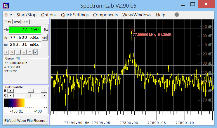
Screenshot from a 'frequency check' using DCF77 (German time signal broadcast on 77.5 kHz).
Too large frequency error, almost 5 mHz at 77.5 kHz ! Reason: ADC-clock in an SDR-IQ was not 'calibrated'.
If the measured frequency differs too far from the expected value (see 'stability requirements'),
check the sampling rate, and -if external frequency conversion is used- make sure the VFO- and BFO-frequency
of a the external receiver are sufficiently stable or (ideally) all locked to a reference.
Let the high-resolution spectrogram run for several hours to check for drift. Below a screenshot made with an SDR-IQ,
with the stock 66.66 MHz oscillator attached to a temperature-regulated heater (transistor as heater, NTC as sensor):

12-hour spectrogram showing the DCF77 carrier. Initial drift ~2.5 mHz, ~30 ppb, after starting.
Almost no drift when the room temperature was constant (between 06:00 and 17:30 UTC).
After turning on the central heating (~17:00 UTC) drift showed up as narrow-band 'noise',
which confirms the simple temperature stabilisation of the SDR's oscillator is not sufficient.
4.2 Switch back to the EbNaut (radio-)frequency
After checking the frequency with a 'strong' reference, set the NCO frequency back, close to the frequency of the expected EbNaut transmission.
For SDRs like SDR-IQ, it's advisable not to set the SDR's NCO frequency exactly to the center of the EbNaut transmission,
because any residual DC component entering the A/D converter, or caused by an offset in the A/D converter, generates a weak peak at '0 Hz' in the decimated baseband signal.
For SDRs witn an 'analog' frontends (e.g. FiFi-SDR, and similar simple downconverters which do not digitize the RF input but
the downconverted, low-pass filtered analog I/Q signal), the 1/f noise caused in the analog circuitry
will deafen the receiver near 'zero beat'. The decimated signal (saved in the wave file for the EbNaut decoder)
covers some ten Hertz of bandwidth (depending on the IF sampling rate and the FFT decimator settings),
so you won't lose anything by slightly 'detuning' the NCO frequency.
The EbNaut decoder can be instructed via command line where to look for the PSK signal anyway,
including the 'Radio Frequency offset' saved in the wave file header.
- Note
- For that reason, set the 'VFO' frequency field in SL to the correct value,
even if you cannot control your external LF/HF radio from Spectrum Lab and a soundcard is used for input.
With the external receiver set to upper sideband, type the receiver's frequency into the 'VFO frequency' field.
Otherwise, you will end up with a wave file containing a wrong 'radio frequency' offset in the wave file header,
causing headaches later when launching the EbNaut decoder.
With the external receiver set to 'CW', things get even more tricky because you will need to add
(or subtract?) the CW 'audio pitch' frequency, depending on your receiver using USB or LSB for CW.
Again, a test with a strong unmodulated carrier is vital to check everything works as planned,
before trying to receive / decode weak EbNaut signals, because you won't see them on the waterfall display
when they're 'weak enough' to be a challenge for the decoder.
4.3 Start and stop recording
You could let the program start and stop recording automatically (on a pre-defined schedule),
as explained in one of the next chapters.
But for a start (without a schedule), click on the gray circle in SL's main menu (which is
the recorder's activity indicator), and select 'Start recording EbNaut_YYYYMMDD_hhmmss.WAV'. The actual filename
contains the current date and time; YYYYMMDD_hhmmss is just a template.
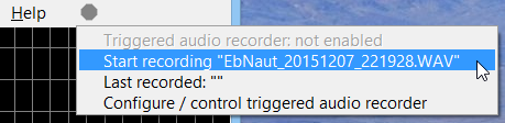
Note: If the 'gray circle' in the menu line is already flashing red, the recorder may have been started via schedule.
You can stop the schedule any time via the main menu:
Select 'File' .. 'Scheduled Actions', and uncheck 'Active' in the dialog.
... to be continued ...
5. Scheduled Audio File Recording
Due to the propagation (and QRN, i.e. sferic activity) EbNaut experiments are usually scheduled late at night.
To avoid getting up every few hours just to start a new recording, or invoke the decoder, you can automate this
using SL's 'periodic' or 'scheduled' actions. The screenshot below shows a simple example, which begins a new
audio recording each day at 22:00, 00:00, etc (all times, as usual, in UTC):
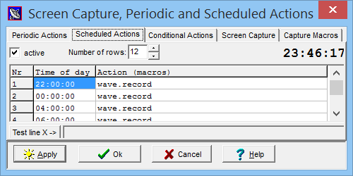
Note: The interpreter command 'wave.record' also stops recoring the previous file.
In other words, it 'produces a new' whenever it is invoked.
To launch the EbNaut decoder (at a certain time-of-day), you could use SL's exec-command
in the table of Scheduled Actions.
To start recording without a schedule (manually), click on the gray circle in SL's main menu (which is
the recorder's activity indicator), and select 'Start recording EbNaut_YYYYMMDD_hhmmss.WAV'. The actual filename
contains the current date and time; YYYYMMDD_hhmmss is just a template.
... to be continued ...
6. Sending EbNaut with Spectrum Lab (off topic, but a requested feature)
SL does not have an integrated EbNaut encoder, but the digimode terminal can be configured to send a sequence
of 'ones and zeroes' generated by Paul Nicholson's encoder (for Windows, use ebnaut-tx.exe).
How-to..
- Generate the message with the encoder (ebnaut-tx.exe). Save the encoded stream of 'ones and zeroes' as a text file, e.g. test.txt .
- Make sure the output to the soundcard is enabled (in the circuit window, the 'DAC' block must be green).
- Open SL's digimode terminal.
- If not done yet, disable sending pre- and postamble unter 'Settings'..'Rx/Tx switching options'.
- Under 'Settings'..'Digimode Configuration, set 'Encoding' to 'None (one-to-one), not 'Differential'
- On the same panel, set 'Codeset' to 'Unknown, emit '0' and '1' (which also applies to transmission)
- Select a suitable audio frequency for your transmitter, and the correct symbol rate.
- Load the file generated by ebnaut-tx.exe (guess where.. in the 'File' menu, of course).
- Select 'Mode'..'Transmit', or click the 'Rx/Tx'-button to switch to transmit when it's time to...
or use the scheduled actions to automate this.
Beware: There are several pitfalls ! Even if the same soundcard, connected to the GPS sync signal,
is used to generate the output (in 'full duplex mode'), it's not guaranteed that the DAC's
sampling clock is fed from the same source as the ADC's sampling clock (hard to believe, but unfortunately true).
So even if the frequency test for reception was ok, and the soundcard input's sampling rate
is continuously monitored and drift compensated via software, the analog output may not be stable enough
for EbNaut's stability requirements. A dedicated hardware (DDS with GPS-locked source, etc) is a better choice !
back to top