The Vertical-L-Antenna ("up-and-outer") by DK7ZB
|
The starting point of the considerations was the question how much radials a vertical antenna actually needs. The version of the vertical 90 ° dipole described here is also very popular as an “up-and-outer” for portable fans. It only needs one counterweight. This is the reason to take a closer look at this antenna and to develop a version that covers the bands 10-40 m. Theoretical considerations The vertical L-antenna is obtained by bending
the classic half-wave dipole in the middle and leading one section
vertically upwards and the other parallel to the ground. In the free
space, this angular dipole has an impedance of 45 Ohm, the length
must be increased by approx. 3% compared to the strechted normal
form. Analyzes with EZNEC
Such antennas, which are fed off-center are
called "OFC" antennas. Since they tend to common waves (like the
classic Windom antenna too), they must be connected via a current
balun. |
 |
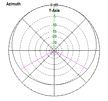 |
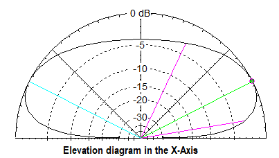
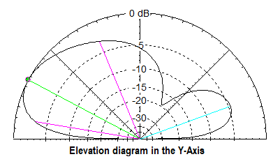
All diagrams for 14 MHz The azimuth diagram (i.e. viewed from above)is not circular, there is an attenuation of 5 dB on the side opposite to the horizontal wire. If you have a preferred direction in mind, the counterpoise should be aligned in this. The "gain" in this area is -1.5 dBd. As with other vertical antennas, this appears to be very little. This is compensated for by the flat elevation angle. In comparison, a horizontal half-wave dipole at a low installation height produces a lot of useless high-angle radiation, which is counterproductive, especially on the lower frequency bands. The elevation diagram is therefore not symmetrical. Despite the low overall height, the radiation diagram is quite DX-compatible. The up-and-outer can also be fed with a two-wire line. In this case, both sections should be 7 m long. This enables operation of 10-40 m, but only with an antenna tuner.
|
|
Practical structure |
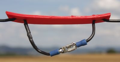 |
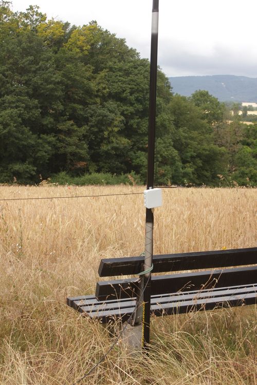
For this I had assembled 50 mm long epoxy sections, through which two holes were drilled on each side for strain relief. The wire is pulled through as a loop. Surprisingly, the resonances, especially on the higher bands, were significantly below the previously determined lengths and the respective SWV minimum was also significantly worse than before. Obviously, the free hanging ends play a serious role and have a negative impact on the properties of the used band. Then I made the insulating pieces much longer and enlarged them to 120x20 mm.The picture shows this method with the “jumpers” used. |
|
I then used a 2.5 mm thick carving board made of PE as the material, which can be cut with sturdy scissors. When opening the bridges, the ends of the wires must be bent as far apart as possible to prevent the undesired coupling mentioned. Now the result looked much better, even if the lengths are still slightly shorter than with the pure mono-band construction. |
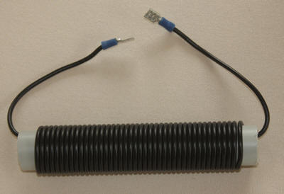 The 10uH-coil for 7 MHz |
 |
|
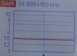
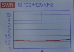
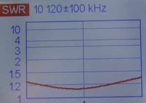
I have summarized the finally determined dimensions of the wire sections in the table. The inductance for 7 Mhz is approximately 10 uH and is made from the same installation wire as the band sections. For this purpose, 42 windings are applied to a PVC pipe with 25 mm outer diameter (Figure 7). This coil is inserted with the jumpers between the 10 m and 12 m sections of the vertical part . I have put the resonance in the lower half of the band at 7 Mhz, so that CW is still possible with good SWR. If you shorten this section by 15 cm, the best fit is between 7.0 and 7.1 Mhz. Alternatively, you can make this shortened piece even pluggable and let it hang down in the end. Since changing the frequency to 40 m requires only the tail of the horizontal part, which is easily accessible, this is a good option. |
|
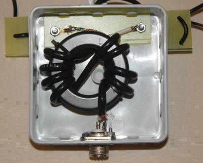
Because the two antenna halves have different environmental conditions, in addition to the above-described effect of the off-center feeding common waves can be expected. For this reason, a balun should be provided in the feeding point. This consists of 2x4 turns Aircell-5 on a toroid FT240-43. So you are up to a power of 1 KW on the safe side. The picture shows the junction box with the built-in toroid. It makes sense to connect the vertical conductor on the inner conductor of the coaxial cable and the horizontal part on the shielding. If you only want to work with smaller powers up to 200 watts, then RG316U teflon cable with 2x5 turns on a FT140-43 offers. If necessary, you can also use the inexpensive and easily procurable RG174 up to 100 watts.
|
 |
Correction Lengths/100KHz |
Adjustment and operation
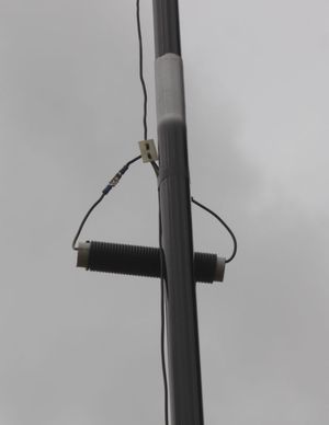
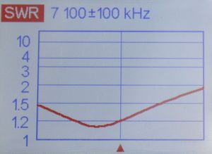
First, you connect the individual sections with luster terminals, so you can easily make length changes. Start from 10 m and then shorten the ends again slightly, when the metal sleeves of the couplings and connectors are soldered. Then you go to the 12-m band and proceed accordingly with all other bands. So you can put the best fit in the preferred areas. Up to 10 m, where I have selected 28.0-29 MHz, a balance is just below the mid band. The measured SWR gradients on the different bands are documented in Figures . Feeder cable was 10 m H-155. With a ground socket the GRP mast can be set up, for the second leg one uses a tree or fence. If necessary, there are also other attachment points. If necessary, a short auxiliary mast is used for bracing. It is important that this half of the antenna, as shown in Fig. 17, is parallel to the ground at a height of 1 m and does not descend obliquely, because this results in shifting the resonance again. To change the band, the mast is folded over and the corresponding connectors are opened or closed. This is easier with the horizontal part. However, one thing has to be pointed out: As with all antennas that are set up near the ground (the "counterpoise" is only 1 m high!), The impedance and resonance strongly dependent on the ground conductivities. On dry sandy soil can be compared to wet meadow floor quite different. That's the price for the simple construction. On the other hand, a correction within certain limits by height change or ground angle of the horizontal portion is possible. It should be noted that with a smaller distance, the impedance is shifted upwards, with a larger downwards. The resonance is exactly the opposite. |
 |
 |
 |
 |
 |
 |
 |
Sources: [1] Steyer, M. (DK7ZB): Auf dem Weg von der
Vertikal zur Inverted-T-Antenne, FUNKAMATEUR 62 (2016), H. 9, S.
853-855 |