Wireman-J-Poles

The Vertical Sloping Dipole

The CE0Y-7-m-Triple-Leg

Vertical 2x7m-Double-Zepp

The Battle-Creek-Special The C-Pole

The C-Pole-Antenna, Examples for 14 and 50 MHz (by DK7ZB)

Rate this site
The DXZone.com

(with 10 = top)
The C-Pole had been described first by Brian C. Cake (KF2YN) in QST 2004, No. 4, P. 37-39 "A Ground Independent  Vertical Antenna".

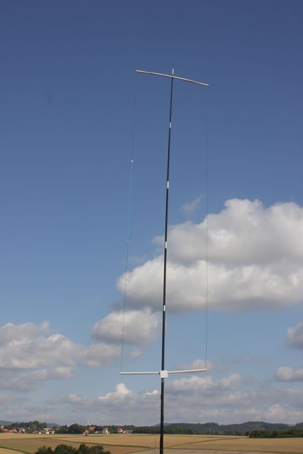
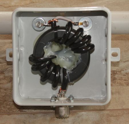
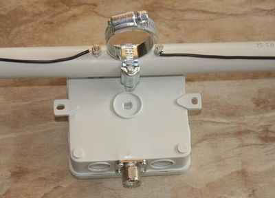
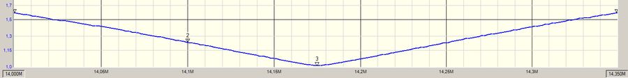
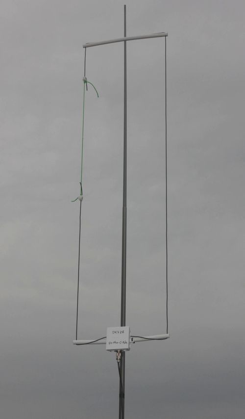
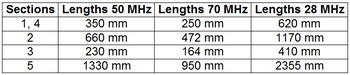
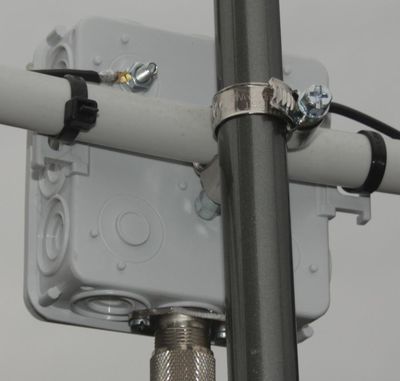
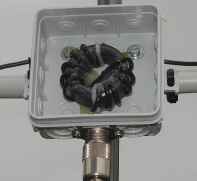
It is a folded half-wave dipole with an asymmetrical tapped 50-Ohm-point in the lower part of the antenna. I have modified the C-Pole for a greater bandwidth. Therefore the parts 1 and 2 are longer than in the original description and the gap between parts 2 and 3 is greater. The dimensions are < lambda/4 in the height and it is easy to build.

It is a special type of an "OCF"-Antenna (Off-Center-Feed). These antennas show a tendency for common waves. For this reason it is obligatory recommended to use a current balun for the feeding.

I have built the C-Poles with insulated 1,5 mm2-Copper-wire. For the sections 1 and 4 I have used insulated PVC-tubes as spreaders and support for the wires.

The gain of the antenna is -0,75 dBd in free space. With the balun the antenna handles 1 KW HF SSB/CW.


The 20-m-C-Pole

With the dimensions in column 2 it is possible to build C-poles for other bands

The patterns above ground:

Red = 3 m (Elevation 20°)

Blue = 4 m (Elevation 18°)

Left: The current balun, 2x4 turns Aircell-5 on FT240-43

Right: Mounting of the PVC-tube with  two clamps and the balun box

Adjustment of the Antenna

When the resonance  of the antenna is set to 14,175 MHz, the SWR remains <1.6 over a bandwidth of +/- 175 kHz. If the resonance point is just below, it usually suffices to make a correction by shortening the section 3. In the opposite case, it must then be extended accordingly.
If a clear resonance is present, but further from the 14,175 MHz, it must be noted that the two unequal antenna sections are varied in a ratio of 3.6:1. This may be the case when using other wires.

It is more difficult if there is a clear resonance point in the desired window, but the SWR is too high. This indicates a feedpoint resistance which differs from 50 W. An analyzer can be used to determine whether it is too high or too low. For R> 50 Ohm section 2 has to be lengthened and 3 has to be shortened, if R <50 Ohm, then you lengthen 3 accordingly and shorten 2. Only with a SWR measuring system is systematic experimentation determined to get the correct direction. It is relatively easy to find out the right lengths, too.

The C-Pole-Antenna for the 50-MHz-Band

The balun is wound with 2x5 turns RG178 on a FT140-43 core and handles 100 Watts. For more power

use the balun as described for the 20-m-C-Pole. Wire is 1,5 mm2 PE-insulated copper.

The Lengths for the Bands 6 m, 4 m and 10 m