 |
|
|
I recently acquired an early IC-781 that a local ham had for sale. It appeared to be in pretty good shape and was in daily use; the owner knew of no problems. When the rig was set up on the operating desk, I first checked the maximum output power on all bands and found that 17 meters was low (117W out) and 12 meters produced some odd symptoms. When sending a string of dits at 110W output, all was fine, but cranking up the drive from there resulted in the meter lamp beginning to blink and the CRT image jittering. At 120W, it was clear that something was seriously wrong, as the CRT image was reacting as if the power were being turned off and on quickly and the I could hear a relay or two chattering inside the IC-781. The collector current to the finals, as measured by the IC-781 meter, was higher on 12m than on 15 or 10 meters, and I thought the problem might be an over-current protector on the verge of shutdown.
A query on the Icom reflector led me to the IC-781 technical info at the Icom America site. While I was aware of the possibility of heat damage to the regulator board of the IC-781, I was surprised to read that Icom was recommending that IC-781 service centers always check that area first when a unit comes in for service. Since the nearest service site was 1000 miles away, I decided to tackle the job myself. I figured I could do the repair for less than the cost of shipping the IC-781 both ways.
The service manual is a must for such a project, and I had no luck finding an original for sale. Adam VA7OJ recommended the manual download from the Icom FAQ site, and a family member with high-speed Internet access downloaded it for me. The manual is in .PDF format, and was of much better quality than I expected. The schematic diagram quality is marginal in some places, but with the help of magnification, you can usually decipher the lettering on component labels.
The regulator (REG) Unit itself is housed in a cast aluminum compartment on the right rear of the IC-781. It's directly next to the final amplifier (PA) unit. Unfortunately the regulator housing is not ventilated, and the heat builds up owing to the presence of several hot-running regulator devices. In order to check out and repair the unit, you must remove many screws and the service manual diagram is very helpful here in identifying the right items to remove. One of the regulator modules which are fastened to the housing must be insulated from ground, and a mica spacer is used with that one. Note carefully which module uses the spacer, since there are three other regulators that do not use one.
When the board is loose, remove the high voltage (30VDC) wires (one red, one black) that supply the PA stage. These are secured to terminals in the PA compartment using screws and ring terminators, and so are easily removed. At this point, there are still several wires connected to the regulator board, and you must unsolder these from the board in order to remove it from the IC-781. Thankfully, the wires are terminated in very small metal tips that keep the wire strands under control and allow the de-soldering operation to be done pretty easily. After removing the solder around the wire tips, the tips can easily be pushed through the board with a small pointed awl.
After years of struggling with cheap soldering pencils, I finally bit the bullet last year and purchased a Weller WTCPT temperature controlled iron. There's no substitute for an iron of this type when de-soldering or soldering circuit boards. The very small tip can deliver large amounts of heat without overheating components or the board. For de-soldering, I strongly recommend a good de-soldering braid that has plenty of flux embedded in it. There’s a vast difference between the braid that Radio Shack sells, and the Chemtronics “Chem-Wik” brand that I bought from Digi-Key. I used the .030 size, and it really sucks the solder off connections quickly.
Upon inspection of the regulator board, I could tell that someone had been in there before me, as clear RTV compound was smeared between the four electrolytics and the L7 coil. Icom recommended the RTV to repair centers as a means of minimizing movement of the L7 coil which is not secured to the circuit board except via its two heavy leads. Not a good design, as the coil is a bit heavy and will rock back and forth, cracking the circuit board traces to which its leads are soldered. It makes no sense to secure the coil to the caps, as they themselves will move a bit due to their mounting method. Clearly, the RTV should be applied between L11 and T2 which is secured to the board via many soldered pins and will make a much more substantial anchor point.
The first thing I inspected was the circuit board land patterns for L7, and just as Icom said, one of them was badly cracked. There was still continuity, but the remaining copper bridge was very narrow indeed. (See Fig. 2 below.)
There were a couple of scorch marks on the circuit board, and I had intended to replace only the 4 or 5 components the Icom literature recommended (L11, C4, C28, R35). However, after pricing out the electrolytics, I decided to replace all of them before reinstalling the board. (Removal of the regulator board was something I didn’t want to do again!) The total price for replacing all the electrolytics (from Mouser) as well as the L11 coil and R35 (from Icom) was less than $25. I learned something here - the electrolytics were all high temperature rated (to 105°C), while normal electrolytics are rated at 85°C. That increases their price only slightly, but makes it just a bit harder to find all the values you'll need.
Another key item is to re-solder the ends of the small metal bar shunt in the over-current sensing circuit. This bar is a resistor of only 0.001Ω, so it is very important that the bar-to-land pattern junctions be as low-resistance as possible. It is on the underside of the board, about 1" long.
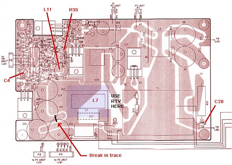 |
Fig. 1 is a component-side layout diagram of the REG unit circuit board. The broken trace is on the other side of the board where indicated. Components C4, L11, R35, C28 are most prone to heat damage according to Icom, and should be replaced. The blue-shaded rectangle at L7 represents the approximate size of L7, while the smaller inner rectangle is the footprint where L7 contacts the circuit board, and I covered that portion of L7 with RTV compound. I filled some of the space between L7 and T2 (indicated by “Use RTV Here”) with a large glob of RTV, which should help minimize any movement of L7.
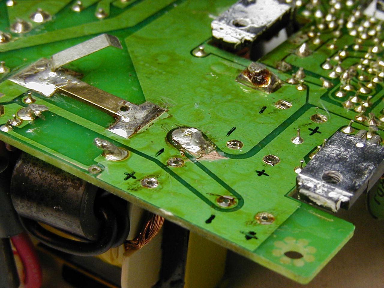 |
Fig. 2 shows the damaged land pattern on the board. One of the leads from L7 connects to the point in the center of the photo. You can clearly see that the trace is broken from the movement of L7. Only a small section in the center of the trace is intact – maybe 20%. The soldered portion of the trace has been lifted off of the board a bit and the board underneath has been worn away some from years of contact with the moving trace. To the left is the 0.001Ω metal bar shunt, already re-soldered at both ends.
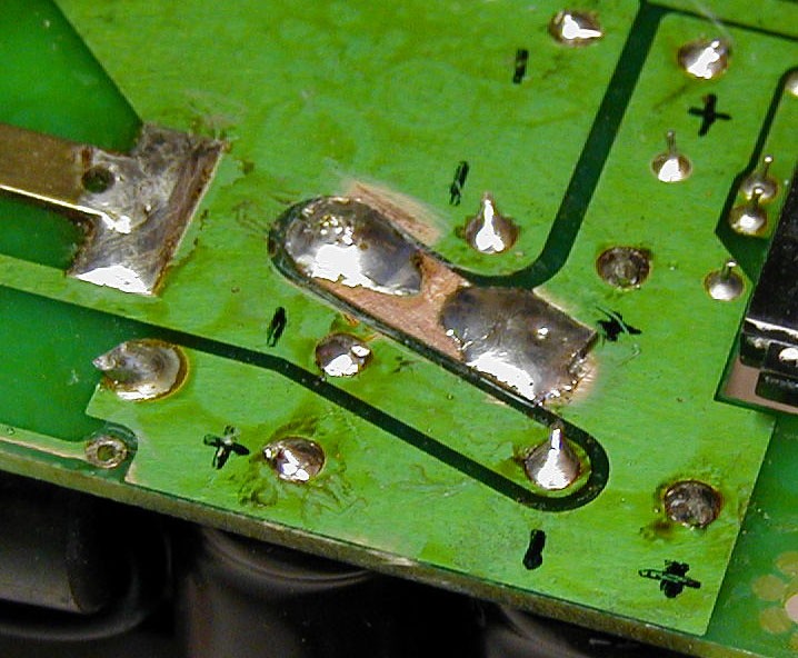 |
Fig. 3 shows the repaired trace. The broken-off trace piece was removed and the green coating on the board beyond was scraped away. I then tinned the newly bared copper trace area. The patch was made using a piece of scrap copper ground strap which I shaped using a nibbling tool and file. The underside was tinned where it mates with the old trace to make soldering the two together very easy.
On my unit, the heat sink compound was pretty dried out and hardened; I cleaned all of the old compound off and coated the regulator modules with some new Radio Shack heat sink compound.
I removed the large L7 coil from the board completely, and decided it needed something more than its leads to secure it to the board. After cleaning the board where L7 mounts, as well as the bottom of L7 with alcohol, I put a thin coating of RTV on the bottom of L7, pressed it firmly onto the board and allowed it to set up overnight.
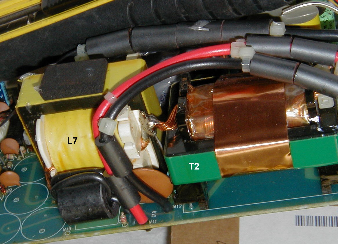 |
Fig. 4 is a view of the REG Unit board showing the positions of L7 and T2, with the electrolytic capacitors to the left of L7 removed. After securing L7 to the board with RTV, the gap between L7 and T2 was filled with RTV to further minimize movement of L7. (This picture was taken prior to the RTV application). In stock form, L7 was held in position via one heavy lead on the left side of L7, and the other heavy lead which can be seen soldered to the lead from T2. Movement of L7 was transmitted to the circuit board trace through the left lead, causing the trace to flex and break.
When the regulator is repaired, there are two adjustments that you must make in the regulator compartment: Setting the 15V regulator output level, and setting the 30V regulator over-current protection level. This is more complicated than you might think because you must connect an appropriate load to those supplies. For the 15V supply, you need only a 40 watt resistor in the range of 5.6 to 6.8Ω. The 30V supply is another matter, as you need to be able to accurately measure the current draw as well as be able to dissipate the heat produced. That load must be 1.66Ω at 540W. Do not even think about using the Ic position of the IC-781 meter to monitor the current. That, as well as the Vc metering function, is probably more than a little bit out of calibration.
Unless you have access to a high current DC meter, you'll need to devise a way to measure 18A, and the easiest way to accomplish that is with a meter shunt. Those are available surplus, and typically produce 50mV across them at the rated current. At Surplus Sales of Nebraska, I found a 20A shunt rated at 100mV drop at 20A. All you need then is an accurate millivoltmeter to measure the drop across the shunt. The 6.8Ω resistors I obtained were just a bit on the low side, and the resulting resistance measured 1.67Ω. With the 30 V supply, that gave me 17.96A which was close enough to the 18A target.
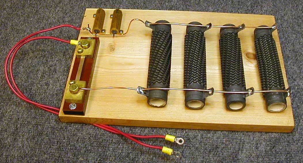 |
Fig. 5 shows the 1.67Ω resistor bank, hastily constructed on a board. On the left is the meter shunt across which you measure the voltage drop with a DVM. The red and black 30VDC leads running from the regulator compartment to the PA compartment were removed from the PA terminals and connected directly to the #12 stranded leads shown here. The gold Dale resistors in the upper left are 0.2Ω 40W units that I was going to use to fine-tune the load resistance if required.
When making the 30V regulator adjustment, you must monitor the DC voltage across the resistive load. I expected the regulator to drop very suddenly as I adjusted R6 on the regulator board. But instead, the voltage decreased over a small span of rotation of R6. I set the adjustment at the point where the voltage first began to dip below 30V.
Since I had to wait for parts from Icom, I also ordered the Sherwood Engineering cooling fan kit for the IC-781. The fan assembly includes a new outer black metal housing which replaces the original regulator cover, and even has the rear connections screened on top as the original had. It also includes the inner metal shield, which is drilled with ventilation holes directly in front of the fan position. This is a top-quality product, and should prevent future regulator unit failures. I found the fan produces a bit more background noise than I would like, so I may increase the value of the resistor in series with the fan to reduce the speed a bit. A word about Icom Parts: I’ve never run across a manufacturer’s parts department that offered more pleasant and quality service than Icom’s does. They quickly ran down replacement part numbers for superseded parts, and they shipped very quickly. If you ask nicely, they’ll even send small parts via USPS Priority Mail for no extra charge. When you order from them, be ready with the Icom part numbers as shown in the Service Manual.
While I had everything apart, I decided to make the latest modification to the IC-781 ALC circuit to eliminate the well-known spike. I needed to change a resistor on the IF board, and one on the PI board. I did the IF board first, thinking that would be the toughest, since there were many cables to disconnect before the board could be removed. It turned out that the PI board change was much worse, as the unit is buried under the scope module, and even getting all four mounting screws out was a challenge. It turns out that this was good experience, as you need to check the regulator output voltages at connectors on the PI board.
When I set the regulator over-current protection level, I found that the meter Ic indication was off by a couple of amps, and that the Vc reading was 1V low. After reading through the Adjustment section of the Service Manual, I decided to run through almost all of the receiver and transmitter adjustments. That proved to be a long drawn-out process, but I was able to find and correct several adjustment problems that otherwise might have gone unnoticed for a while. For example, the actual power output was low, while the IC-781 meter was reading about 30W high. The combination meant that my IC-781 Po meter reading was off by 30% on some bands. I also adjusted the scope center frequency on the three ranges. That can be done by observing a marker signal on the scope while making the adjustments.
I was able to do just about all of the alignment without any special test gear. Here’s what I used:
Ancient HP 200CD audio oscillator
Old Beckman bench DVM (good millivolt measurement capability)
B&K Precision 5380 DVM
Bird 43 wattmeter with 250 watt slug
Oil-filled paint can dummy load
At the suggestion of Adam VA7OJ, I used the IC-781 Service Manual available via download in PDF format from the Icom FAQ site. With a decent inkjet printer, just about everything (including the schematics) is readable. On those schematics which include notations of voltages and waveforms, much of that information is difficult or impossible to read because the original was printed in a color that does not copy very well. Icom no longer carries originals of the IC-781 Service Manual.
The repairs took quite a bit of bench time, but are certainly not impossible to do if you are technically adept and want to save some money. I’m very glad that Icom took the time to publish their list of common service questions, as I could never have figured out the solutions on my own.
If you have an IC-781, don’t have the Sherwood fan and have never had the regulator board serviced, you can probably count on experiencing regulator-related problems in the future. As was pointed out to me, the IC-781 was designed to run on a line voltage of 100V and uses a shunt regulator, which means that it is pouring out lots of heat even when the IC-781 is in receive mode. When you power it with 120V (my line voltage is a high 124.5V most of the time), the heat generated will increase by 44%, much more than can be safely dissipated from the sealed regulator compartment. You can probably forestall the inevitable by reducing the line voltage to 100V by using either a separate low-voltage transformer with its secondary connected so as to buck the line voltage, or by using a Variac adjusted to 100V. You can often find nice enclosed 10A Variacs for around $100 on eBay.
Effects of Line Voltage on Icom IC-781 Power Supply/Regulator Heating
"IC-781 & IC-R9000 technical and maintenance issues" by Traian Belinas, YO9FZS
Copyright © 2004-2017 Floyd L. Sense K8AC (including images). All rights reserved.
Page created by A. Farson VA7OJ./AB4OJ. Last updated: 10/10/22