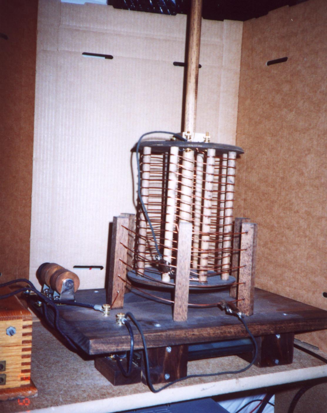
The design is that of a traditional inductively couple spark gap transmitter utilizing a simple straight gap and oscillation transformer. The HV source can either be from a induction coil or a HV transformer. The first picture shows the basic construction. The primary of the oscillation transformer is the large 4-turn coil that passes thru 6 posts which are 5.5" high and 3/4" square. The pitch of the primary is 1" between turns. With the homebrew glass plate capacitor of .003 uf, underneath the base of the coil, the frequency of transmission can be caried from 1000 khz to 2250 khz by adjusting the primary tap.
The secondary of the oscillation transformer consists of 15 turns of #14 awg copper wire on a 7" diameter former made from 8 1/2" wood dowels and some circular top wood pieces. Two binding posts on the top of the secondary would theoretically be connected to the antenna and ground. A clip on the secondary allows tuning of the secondary inductance to resonance with the primary. The secondary can slide up and down along a central rod, about 20" in length, to vary the coupling. The capacitor consists of alternating layers of heavy gauge aluminum foil and six 8" by 10" glass plates. The gap is a nifty adjustable Fischer 1 Kw air-cooled gap ( with cooling fins ) scavenged from a defunct diathermy machine. It is mounted right on the wooden base.
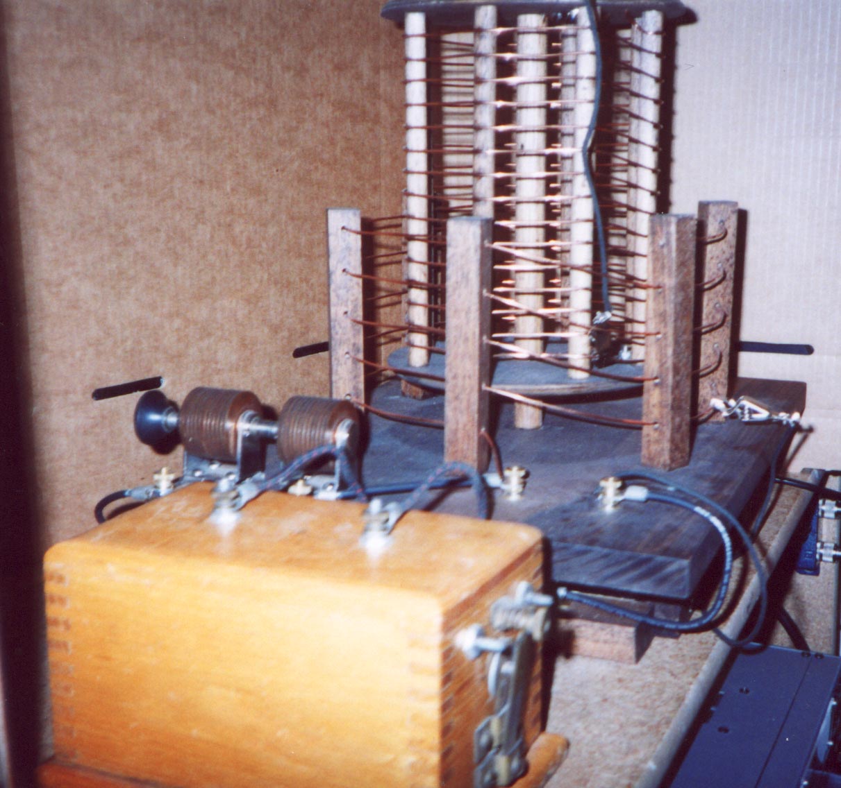
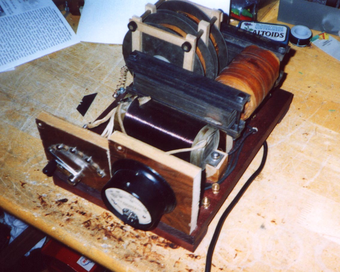
The picture above shows the transmitter with an Electroimporing Company spark coil. For higher powers, a high voltage transformer with reactance regulator can be used. This is shown in the picture below. The reactance regulator is the heavy inductor immediately behind the AC amp meter. It is tapped so that the current supplied to the primary of the transformer can be varied.
I've done a bunch of experiments with this transmitter into a dummy load to evaluate bandwidth and to learn how to "tune" and adjust the spark gap transmitter. As time permits, I'll post the results of my experiments in this page.
A rotary gap is in the works.
Details of Construction, with induction coil HV source:
The "battery":
Here I used a run-of-the-mill DC regulated power supply, capable of delivering 2 amps between 6 and 12 volts. This is not at all critical. Spark coils were generally run at these voltages on the primary. I used 7.5 VDC for most of my experiments, as this seemed to work the best with my coil. For all connections between components, I used a heavy gauge ( #12 ) solid conductor insulated wire.
The key:
The key makes and breaks the primary circuit of the induction coil in the form of the "dits" and "dahs" of the telegraph code, and so must be capable of withstanding the primary current. The key contacts for this particular transmitter do not have to be particularly heavy as the average primary current is not very high, so just about any telegraph key will do. For effect, I used the only spark key I own, with big 1/4" diameter contacts.
The induction ( spark ) coil:
The induction coil is the source of high voltage in the spark coil transmitter. Its purpose is to charge the capacitor which is connected across its secondary terminals to the breakdown voltage of the spark gap. It does this at a rate of 40 - 100 times per second depending on the coil characteristics and its magnetic interruptor. The spark coil used in the replica transmitter was the one which was discussed in considerable detail in part 1 of this series. It appears to be a 1/2" to 1" "size" ElectroImporting company coil of early 1920s vintage. Recall that the size of a spark coil is given in inches of spark length, which is measured in air between two needle points across the secondary. Open circuit voltages ( without a capacitor loading the secondary ) from such coils typically range between 11000 and 20000 volts. The loaded voltage is considerably smaller. As the size and therefore unloaded voltage of the spark coil increases, more capacity can be used across its secondary terminals. The power of a spark coil transmitter is proportional to the product of the main tank capacitance, the number of sparks per second, and the square of the voltage on the capacitor. So, for a bigger signal, use a bigger coil! The spark rate can be roughly adjusted by a thumbscrew on the coil's magnetic interruptor. The thumbscrew basically just moves the armature ( an iron disc which is attracted to the coil when the primary is energized ) closer or further away from the iron core of the coil. A small amount of variation in spark rate can be had here. This adjustment is somewhat critical, as there is a point where the interruptor will not function properly. See the discussion in part 1 of the series. Ideally, one would like a high spark rate, both for the increased power produced as well as the higher tone which would be heard at the receiving end. I attempted to measure the interrupters rate of movement using an ancient analog scope of dubious triggering ability but was unable to get a good measurement. By listening to the tone produced in a receiver, I would estimate the spark rate at perhaps 40-50 hz.
The primary of the induction coil is in series with the "battery" and key. The secondary of the coil is connected to the capacitor, spark gap, and the primary winding of the oscillation transformer as shown in figure 1. The spark coil can be seen in the foreground of figure 3.
The Capacitor:
The capacitor is charged to the breakdown voltage of the spark gap and forms part of the resonant "tank" circuit with the primary of the oscillation transformer. The capacitor chosen for this transmitter was of the simple plate glass and foil design. My capacitor consists of alternating layers of 8" by 10" glass pieces ( the kind used in picture frames ) and the heaviest gauge of aluminum foil I could find. The capacitor required 6 of the 8" by 10" glass rectangles. Two of the glass pieces formed the top and bottom of the capacitor. Capacitor "plates" were made by making a 7" by 9" rectangular template of heavy cardstock, with a 1" wide "tongue" extending from one corner of the template. The aluminum foil plates were then cut using this template. Five capacitor plates were required. Two of the foil plates were cut using the mirror image of the template. To construct the capacitor, the base piece of glass was laid down and a spray adhesive was applied to the surface. Then, very carefully, one of the foil plates was "squeegied" onto the glass. Spray adhesive was then applied to one side of the next glass piece and laid upon the first capacitor plate. Then adhesive was applied to the top of this glass piece and a "mirror" image foil plate was "squeegied" onto it. The rest of the stack followed this construction. Note that when the whole thing is done, there are "tongues" extending beyond the edge of the glass pieces on alternating sides between each glass insulator. The "tongues" on a given side are then mechanically connected together and brought out to two binding posts made from 8-32 brass hardware. These form the two terminals of the capacitor. The whole device was built into a poplar frame to hold everything together. As constructed, the capacitance of this device was measured at 0.003 microfarads, and with the 3/32" thickness of the glass insulators, should be able to withstand a respectable voltage. Although it is somewhat difficult to see, the glass plate capacitor is visible in figure two. It lies directly underneath the base of the oscillation transformer. According to "The Junior Operator", July 1920 QST, .003 uf is just about right for a 3/4" spark coil.
The Spark Gap:
The spark gap serves as an electronic switch which "closes" when the potential between its electrodes reaches a "breakdown" voltage. This breakdown voltage depends strongly on the distance between the electrodes. A typical gap used in such simple transmitters would have consisted of two zinc rods, perhaps 1/4" in diameter, mounted in a pair of binding posts. I don't know where to get zinc rods. I cheated here a bit and used a beautiful finned spark gap liberated from a trashed diathermy machine. The gap is a Fischer 1 kilowatt capacity design. It is extreme overkill for this project but it sure looks nice. The gap is fully adjustable with insulated knobs for on-the-fly adjustments. This gap is visible immediately behind the spark coil in figure 3, and is mounted directly on the baseboard.
The Oscillation Transformer ( O.T ):
The oscillation transformer consists of two parts, the primary and the secondary. The primary serves as the inductance in the resonant circuit formed by it and the capacitor. As the spark gap breaks down and conducts, current is dumped into the primary of the O.T. from the capacitor, and passes back and forth between the capacitor and OT primary until the spark gap opens again. Energy is transferred from the "closed" circuit formed by the tank to the secondary of the O.T. The secondary of the OT, together with the distributed capacitance and inductance of the antenna or load, forms the "open" circuit. This is the portion which radiates all of the signal. Both primary and secondary inductances are tapped to permit independent adjustment. By changing the location of the tap on the primary for a given capacitor, the frequency of the radiation can be adjusted. The open circuit is then tuned to resonate at the same frequency as the closed circuit by adjustment of the tap, allowing for an efficient transfer of energy between closed and open circuits. An OT is generally fitted with some means of varying the coupling between the primary and secondary.
My OT was built on a 16" by 11" poplar base, and can be seen in either figures 2 or 3. The primary coil former is built using six 3/4" square dowels, 5.5" in heighth. The six dowels are mounted vertically and equidistant around the circumference of a circle having a radius of 4.5". Five holes are drilled in the center face of each of the dowels, and are 1" apart. The holes are used to contain the wire for the windings of the primary, which consists of 5 turns of #14 solid copper wire. A heavier gauge wire would have been more appropriate, but for ease of assembly the smaller gauge was used. This coil has a calculated inductance of about 4 uh. Using a grid dip oscillator, I was able to determine the approximate resonant frequencies with the .003 glass plate capacitor as a function of coil tap:
0.5 turns = 2.25 Mhz
1.0 turns = 2.10 Mhz
1.5 turns = 1.66 Mhz
2.0 turns = 1.60 Mhz
3.0 turns = 1.40 Mhz
4.75 turns approx. = 1.00 Mhz
So, right in the old 200 meter amateur band!
In the center of the primary coil a central rod, 20" in length and 3/4" in diameter, was attached to the baseboard. The purpose of this rod was to act as a guide for the secondary coil, which was made to slide up and down along the rod to vary the coupling between the primary and secondary. The secondary was made using two 7" diameter wood discs, eight 3/4" dowels, and about 30 feet of #14 solid copper wire. Holes were drilled in the center of each of the discs to accomodate the coupling rod. Then the eight 3/4" dowels, each 7" in length, were attached to the two discs equidistant around the circumference of the discs to form a "bobbin". In each of the eight dowels, 15 notches, about 1/2" apart, were cut along the length of the dowels to serve as guides for the winding. 15 turns of the #14 wire were then wound around the "bobbin". The calculated inductance of the full 15 turns of secondary winding was about 28 uh. Two binding posts, made from 8-32 brass hardware, were mounted on the top disc. One of the posts connects to the bottom of the coil, the other post has a wire with a heavy clip on the end to make the tap connection to the secondary. The antenna/ground or load is connected to these two binding posts. A simple clamping mechanism was devised to allow the secondary to be held firmly in place at a desired distance of coupling.
73 Mark AB0CW