This transmitter had its origins as a conventional shunt fed Hartley oscillator for 80 meters using a pair of 27 triodes connected in parallel; with 300 VDC on the plates of the 27's, I was able to get about 4 watts output ( with decent stability ) for about 18 watts input, about 23% efficiency. Here is a schematic of the oscillator by itself:
Schematic of Shunt-Fed Hartley oscillator using pair of 27s
This circuit will work fine as shown as a stand-alone transmitter. Circuit parameters are as follows: 15K grid leak; tank circuit: 12 turns, 1/4" copper tubing, 2.5" diameter, about 4.75" long, with 540 pf padding capacitance ( tub micas ) and a 60 pf tuning capacitor. For an antenna coupler, I used a 250 pf variable capacitor in series with a coil consisting of 40 turns 18 Awg insulated wire wound on a 2.5" diameter black PVC pipe. I put taps at 10, 20, 30 , 35, and 40 turns. This will tune a 1/4 wave end fed antenna ( marconi antenna), which for 80 meters, is about 67 feet. Incidentally, I use the same tuner, in parallel configuration, to tune this same antenna as a 40 meter "half-wave". The coupler is simply placed in inductive proximity to the tank coil- don't couple the antenna too heavily or the "note" will suffer with this circuit. There is an optimal coupling point whereby stability is good and yet useful output power is developed. Trial and error required here.
Inspired by a George Grammer article in a February 1931 issue of QST magazine, "More power with better frequency stability", I decided to build a MOPA ( Master Oscillator Power Amplifier ) using the two type 27s in parallel to drive a single 865 tetrode. Both tubes were available in 1929, and both are still relatively easy to find and inexpensive. Here is a schematic of the 865 power amplifier:
Schematic of 865 Power Amplifier

The Hartley oscillator is coupled to the grid of the 865 thru a single large 50 pf mica tub capacitor. Fixed grid bias is fed thru a 10K grid resistor and RFC. Screen voltage is from a 25K 25 Watt series resistor from the plate supply. The tank coil for the 865 consists of 20 turns of 14 Awg. insulated wound on a 2.5" diameter black PVC pipe. Tank tuning is done with a 150 pf transmitting variable. The amplifier circuit is very conventional.
Plate supply for the 865 is 550 VDC. Fixed grid bias is obtained from a separate power supply, which I made variable from 0 to about 130 VDC. I experimented quite a bit with the grid bias , and found the best spot to be at about -60 VDC for this setup. The tube is NOT cutoff at this value of bias, and draws about 22 mA key UP. I found the best tap on the hartley tank coil to be at 2.5 turns from the end which connects to the grids of the 27s. At this point, the oscillator is drawing a total of 26 ma at 300 VDC, or 13 ma per tube. Chirp is negligible at this point. Drive to the 865 is optimal at this point too. So, the 27s are run quite a bit cooler than in the stand-alone Hartley application.
I am keying the oscillator in this MOPA, and allow the amp to draw "standby" current when the key is up. However, I added a switch ( not shown in schematic ) in series with the B- line to the 865, so that I can prevent the 865 from drawing current during long periods of standby ( like when I am listening ). I tried keying the oscillator and amp simultaneously, but the chirp was pretty bad, and I don't like to free-run the oscillator and key the amp ( cause I can hear the oscillator in my receiver when I am listening ). The antenna is coupled to the tank coil using the same simple antenna coupler described previously. The coupler coil is placed in close inductive proximity to the tank, maybe 1/4- 1/2 inch away from its end.
On key down, I can load the 865 amp to between 32 and 34 ma at 550 VDC, 18 to 19 watts input. I am getting between 10 and 11 watts of output, for an efficiency of about 60%.
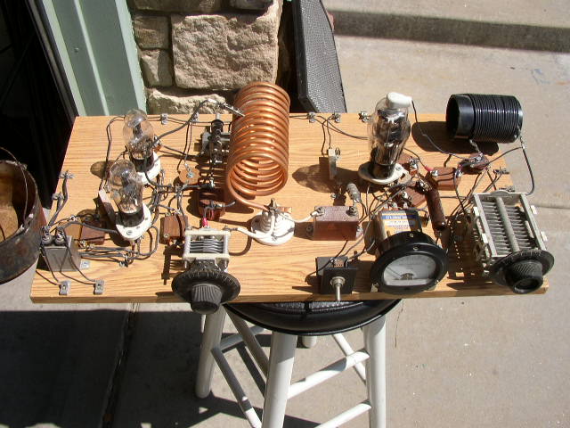
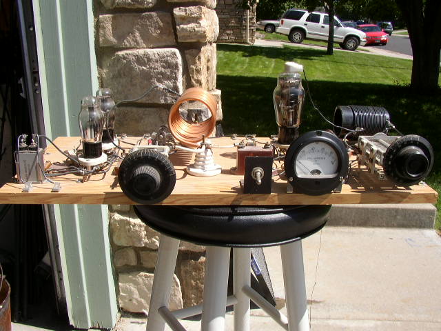
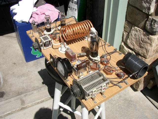
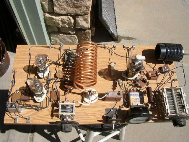
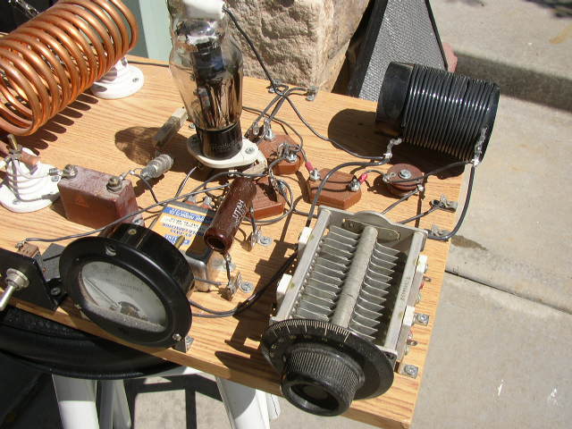
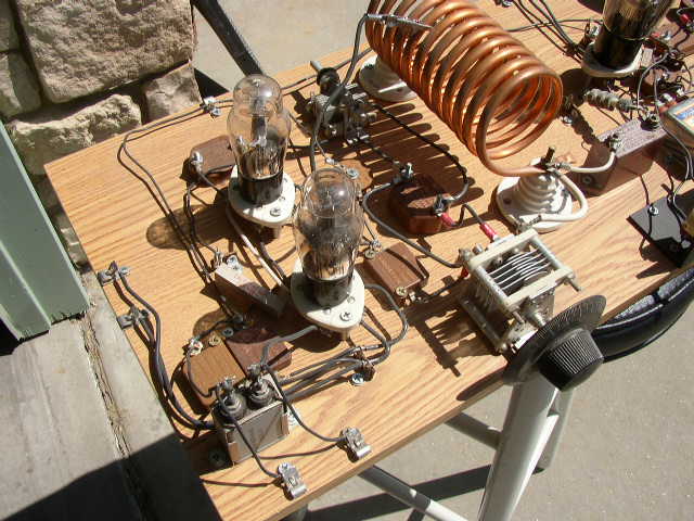
Physically, the whole thing just fits on a 12" wide by 24" long piece of shelving. It looks good when all the tubes light up. The 865 glows brightly, and looks nice with the copper tubing tank coil of the hartley.
This transmitter works great. I have worked stations coast-to-coast with this setup.