
|
Parts List Corrections For The QST Article Q1 is a 3904 C14, 15, 18 are 2.2uF 16V Electrolytic Capacitors C22 is a 0.01uF Schematic Corrections For The QST Article C19 (connected between R14 and pin 5 of U2) should be 0.01uF C20 is incorrectly labeled C19 (connected between R15 and GND) R17 should be R7 C22, again, is 0.01uF These corrections were posted by N1BYT on QRP-L. |
|
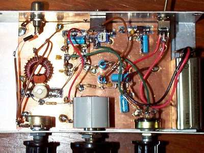
Some Details of My WBR Receiver I did not have an MV104 varactor so I used an ECG 617. This gave me a tuning range of 6.890 - 7.220 MHz. (I haven't tweaked the circuit to cover more of the 40 meter band.) I can listen to CW, SSB, and SW with this sort of coverage. My enclosure measures 3W x 5L x 1.25H. Layout Description From left to right on the Front Panel: RF Gain, Tuning, Regen Control. Directly behind the RF Gain pot is the Wheatstone Bridge / tank circuit. On the Rear Panel directly opposite the RF Gain is J1, the antenna connector. Directly behind the Tuning pot are Q1 and Q2, oscillator and tuning circuits. On the Rear Panel directly opposite the Tuning pot is J2, headphone jack. Below J2 is the Regen Preset pot. Between the Tuning pot and the Regen Control pot is U2 and the audio circuit. Directly behind U2 on the Rear Panel is S1, on / off, and U1 voltage regulator. |
|
Performance Comments I have not had much experience with regenerative receivers, but the WBR is far superior to the others I have built. I was surprised at the WBR's ease of use and the clarity of it's signals. The regen control is very smooth, breaking into and out of oscillation. Audio gain is adequate for headphone use. I have found that even while connected to my 40 meter dipole antenna the RF Gain control is not necessary. I use it fully open without any attenuation. This is a fun little receiver. |