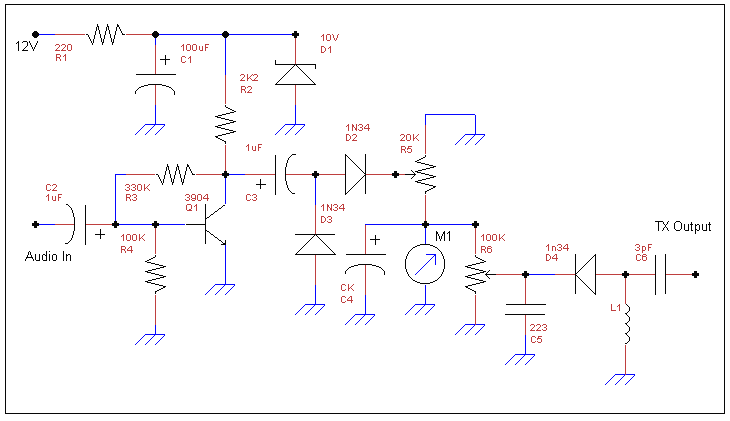
A RELATIVE S METER AND POWER METER

This is one of my pet circuits which I usually put into my homebrew radios. It provides a relative S-Meter and a relative Power Meter. Other than making your homebrew project look a bit more sophisticated, relative metering provides some useful functions. It allows one to electrically compare signal strengths, and, when calibrated to a scale, it provides an indication that the transmitter is functioning properly. The circuit is not my own and I take no credit for it. It was designed by Bill Bartlett, G4KIH, and was originally published in Sprat 57.
Circuit Notes:
1. Old meters taken from CB radios are excellent for this circuit.
2. C4 determines the meter dampening; I usually use 100uF for a nice "soft" movement.
3. Values for L1 are as follows: 80m - 1mH, 40m - 180uH, 20m - 47uH, 15m - 18uH. Although Bartlett did not specify a value for 30m, I have used 68uH and the circuit worked well.
4. Audio should be taken from the input of the audio amplifier.
5. C6, 3pF, directly couples to the TX output. Keep the capacitor lead attached to the TX output as short as possible.
6. Bartlett did not specify the polarity of the electrolytic capacitors in his description of this circuit; I have redrawn the schematic indicating what worked for me. I really don't know if the polarity is important or not in all instances, but obviously it is in some.
7. All the diodes are germanium, except, of course, for the 10V Zener. I have used 9.1V Zeners in my circuits and they work fine as well.


