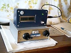
Photo #1 shows how I decided to lay out the project to accomodate my needs. I wanted to use the PLL as a "stand alone" unit to work with various radios and serve as a frequency generator. With that design consideration in mind, I chose to bring the controls of the PLL to a front panel. This photo shows the layout. To the left is the tuning cap shaft (13 - 70 pF) and on the right is the 10K/10 turn potentiometer shaft. The IC sockets in the center will be used with a 10 LED bar graph as a voltmeter (top), and two 8 position DIP switches that I will use as frequency selector switches (center). The smaller DIP switches toward the lower left are used to insert various fixed capacitors into the tuning line.
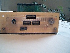
Photo #2 is of the entire unit from the top. The circuitry that has already been built is the 8 MHz reference oscillator. Toward the rear of the unit (left in the photo) is the voltage regulator. My oscillator tunes from 8.186.94 - 8.195.15 MHz. The oscillator was built first and then tested before I proceeded to the next stage of construction.
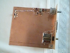
Photo #3 is a closer shot of the reference oscillator. To the lower right you can see the fixed capacitors attached to the tuning cap and the front panel switches.
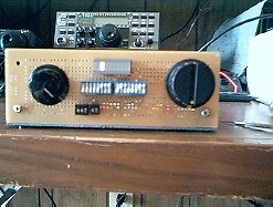
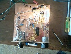
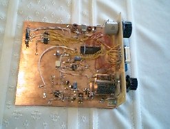
Photo #4 shows the completed front panel layout with DIP switches installed and bar graph LED voltage readout. The LED that is glowing should actually be red. My digital camera didn't pick up the color. On the bar graph readout the first four segments are green, the next three are yellow, and the last three are red. The PLL lock-up voltage will be too low if none or only the first green LED is illuminated, or too high if the second red LED is illuminated (the third LED should not illuminate at all since we're only working with 8V). The PLL will lock in any of the voltage ranges inbetween with 5v - 6v being optimum, corresponding to approximately the third yellow LED. And, yes, that is my Elecraft K2 in the background.
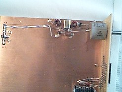
Photos #5 & #6 are of the finished PLL circuit built "ugly" style. The red wires connect the MC145151P2 PLL IC to the DIP switches on the front panel. The yellow wires connect the LM3914 LED display driver to the bar graph display on the front panel. As you may be able to notice, I changed the variable capacitor from a 14 - 70 pF unit to an 8 - 140 pF capacitor. This gives me a greater, sharper tuning range which seems to work better. With this configuration, I have been able to tune from around 5 MHz - 30 MHz. One change I plan to make is to replace the 10 turn 10K tuning pot with a single turn unit, since the greatest tuning range involved is about 22 kHz at 28 MHz.