AA3SJ
Grid Dip Oscillator
Background
I wanted to test the resonance of my 160 meter antenna, but my MFJ 259B Antenna Analyzer doesn't operate very far below 1.8 MHz. I was certain that my antenna was resonant below the range of the analyzer so I built the GDO initially for that purpose. But the project grew a bit. After the GDO was finished I thought it would be convenient to have a frequency counter in the same enclosure. The scQRPion Stinger Singer morse-annunciated counter worked perfectly for the project. I use separate switches for the GDO and the counter so that I can turn the oscillator off and still use the counter. The GDO also serves as a reasonably stable signal generator and a wave absorption meter. Very "cool" for a piece of homebrew gear that cost about $30!
Credits
The circuit I used is the I1FLC adaptation of the GDO published in the ARRL Handbook. I decided to use I1FLC's circuit because it uses plug-in coils only. Other circuits I considered used plug-in coil/capacitor units to optimize oscillation. The only modification made to the original circuit is the addition of a DPDT switch to increase the feedback capacitance of the oscillator. This is C1 in I1FLC's schematic. I switch in 10pF or 33pF. The 33pF, increased feedback, improves oscillation on the lower frequencies. I1FLC's circuit can be found at this site: http://www.multimania.com/pjacquet/gdo.htm.
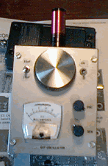
The enclosure measures 4"Wx5"Hx3"D. The potentiometers at the lower left control the oscillation level and the meter sensitivity.
|
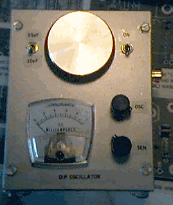
The upper left hand switch toggles the 10pF and 33pF capacitors. On/Off switch is at the upper right.
|
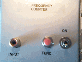
The Stinger Singer controls are mounted on the left side of the enclosure. Phono jacks are used for the coils and for the independent frequency counter input.
|
Coil Details
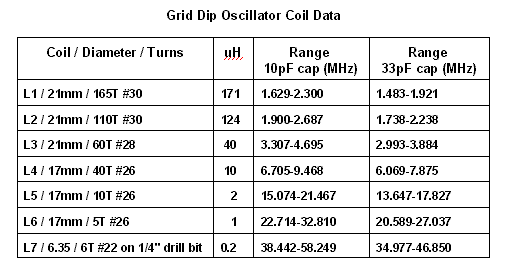
I searched my junk box for appropriate coil forms and finally came up with a novel idea. I used plastic shooters "snap caps." These are 12 gauge and 20 gauge size "fake" shotgun shells, used to protect the firing pin of a gun when "dry firing." The 12 gauge caps measure about 21mm and the 20 gauge caps measure about 17mm, exactly the size used by I1FLC. They are already "center-tapped," since there is a softer plastic insert for the firing pin to hit when it falls. I simply removed the plastic insert, drilled the appropriate size hole and tapped the plastic to fit the threads on the RCA phono plugs. The coils were then wound on the forms. (By the way, probably expended shotgun shells would work just fine as well. Don't use loaded shells. Hi.) After they were wound, I sprayed the coils with a clear acrylic coating to keep them from moving.
My coils were wound with extra turns so that I could remove a few as I tweaked the frequencies. As you can see in the chart below, I have a gap in frequencies between 9.5 and 13.5 MHz. I'm going to tweak L4 to cover a higher range and correct this.
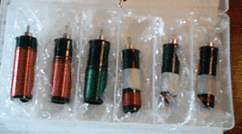
Small plastic box which houses all seven coils.
|
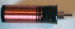
Closeup of the coil construction.
|
Notes and Testing
Notes: (1) The smallest coil, L7, was wound as an experiment to see how well the oscillator would work. The tuning range is far too great to be practical; however, I was able to tune it to the 6 meter band and listen to the signal on my receiver. (2) A vernier drive on the capacitor would be quite useful on the upper frequencies. (3) Over all, I am amazed at how stable the oscillator is up to 28MHz.
Testing: I tested the GDO by building a tuned circuit of known resonance (a 10uH molded inductor soldered parallel to a 47pF capacitor) near 7MHz. The meter scale goes from 0 - 10 units. When I place the GDO coil about an inch from the tuned circuit, the meter dips about 3 units. A bit of playing around is necessary to get a feel for the nature of the dip. There are a few minor dips (not as sharp and not as drastic) as the oscillation level changes while sweeping the frequencies. The "real" dip will be quite sharp and distinct, very noticeable.