Project 'YASSA' - Yet Another Solid State Amplifier
June 2022: This amplifier is an experiment with the MRFX1K80 LDMOS FET to produce a compact 6m amplifier that will pair with my IC-705 ... both as a 'second 6m station' at home, and in a '6m DXpedition package'.
Having heard about 'blown up' LDMOS devices due to an antenna accident or trying to get 'the last mW' (PA running at '101%'), perhaps an analogy about cars is appropriate? They can do 180 km/h, but are safer and more reliable if driven at 100 km/h ... so, while the MRFX1K80 in this project is a 65V 1800W device, it will be run at about 50V and 1000W for safety and reliability.
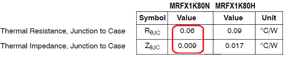
In addition, the MRFX1K80 "N" variant was selected rather than the more commonly used "H" device due to better thermal properties from its Over-Molded Plastic package (OMP). Here is a comparison ...
... and a $30 lower price tag (the same 'stuff' inside, just better and cheaper). What is not to like?
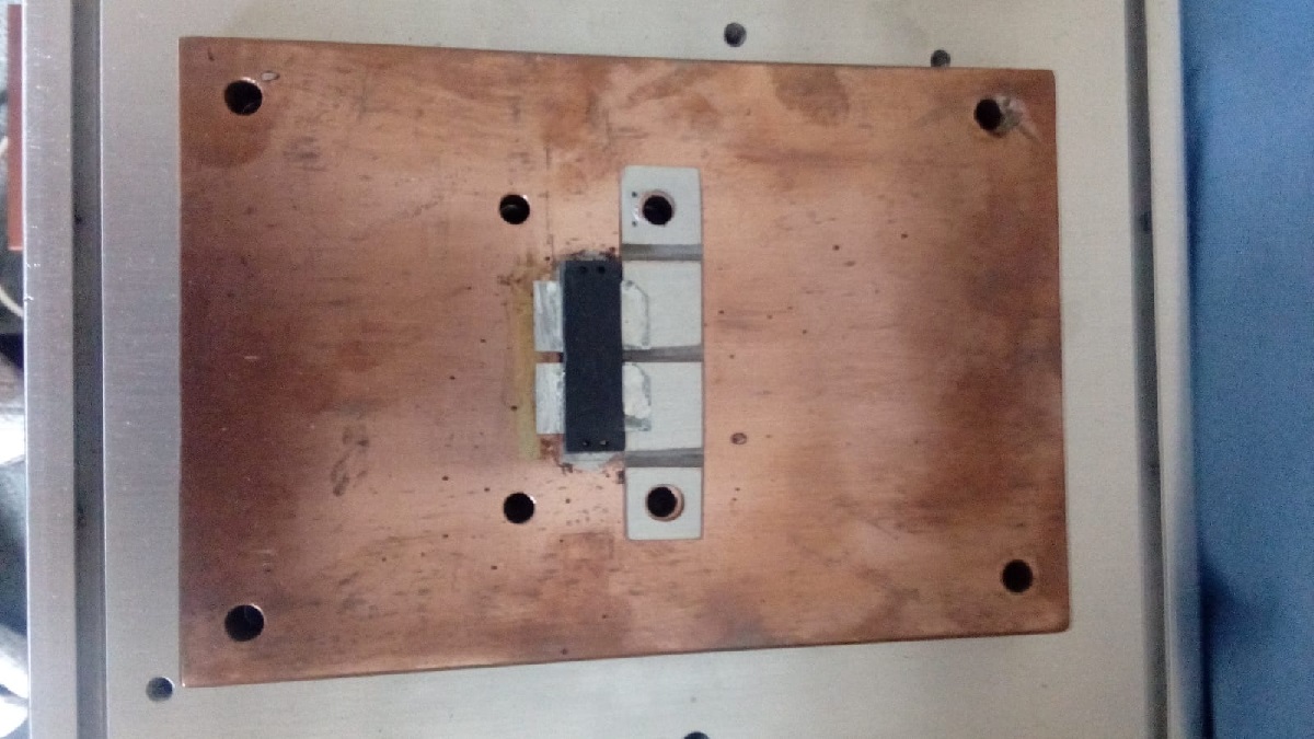
The compomise is that the OMP format is a little more difficult to solder to the copper heat spreader, but NXP/Freescale's AN1907 'Solder Reflow Attach Method for High Power RF Devices in Over--Molded Plastic Packages' has helpful tips.
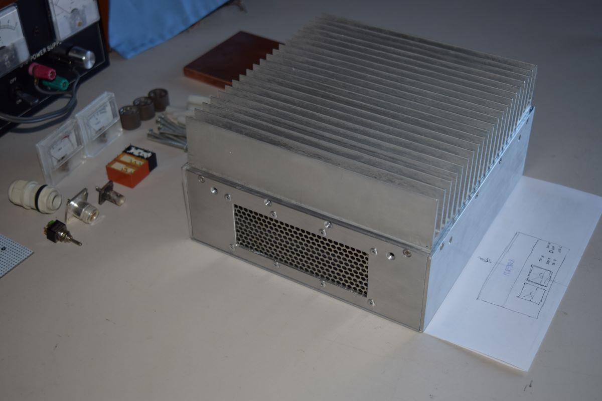
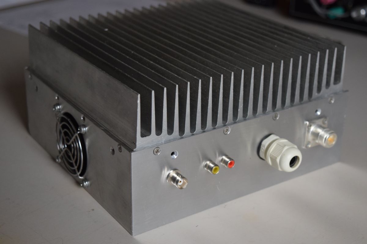
The heat sink chosen from my junk box for this PA is only 210mm x 200mm x 50mm (8.5" x 8" x 2") to keep the amplifier's overall size and weight down. To compensate, two high volume fans will assist with the cooling.
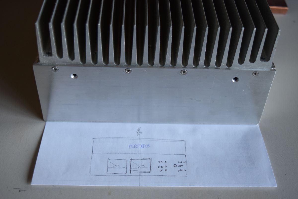
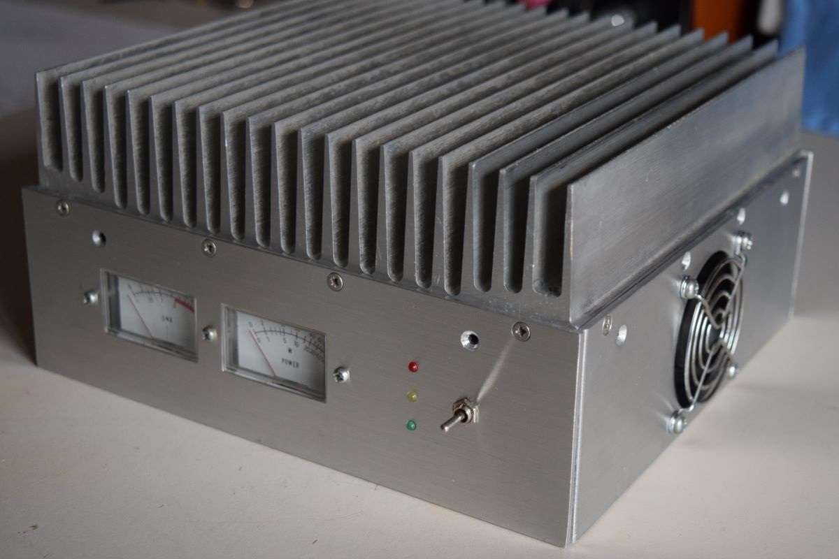
As always, the tedious part of an amplifier build is the metal work, so that is being done first. A case to fit the heatsink is under construction using salvaged aluminium and hand tools ...
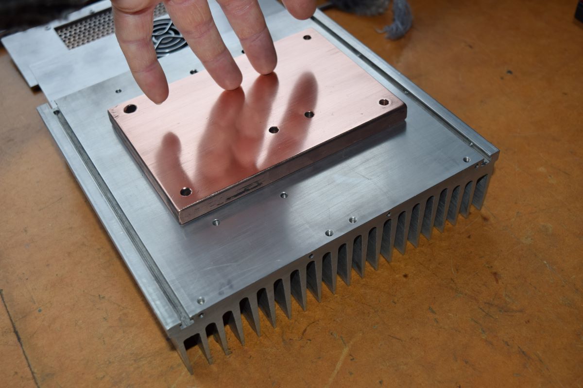
Copper heat spreader block drilled and polished to an almost mirror-finish ...
The MRFX1K80N device soldered to the copper heat spreader block ...
October 2023: The first test on 6m with a simple 1:9 output transformer was not satisfactory. After adding compensation capacitors to the output transformer the amplifier only produced 660W output at 55% efficiency with a 48V supply. As they say, 'more work to be done' ...
March 2024: After another long pause, some further progress on this project. Another output PCB was made to support a broadband output circuit along the lines of the 1.8 to 54 MHz LDMOS amplifier design by W6PQL.
The input circuit was also revised to provide a better match to the driver radio. These changes provided similar results to those obtained by W6PQL ... good power and fair efficiency from 160m to 6m, however there is a lot of extra weight with all the ferrite, and a 'broadband' PA was not my aim.
Upon reverting to the simple 1:9 ferrite transformer output, further 'tuning' obtained 900W on 6m and >1000W on 10m ... better, but still not very efficient (~50%).
The W6PQL style output PC board was then refitted with the intention of optimising it for 6m ... but then the smoke came out! Some solder swarf or contamination along the reused PC board or between the LDMOS drain tabs and ground arced over and 'blew up' the MRFX1K80N device. The 'plasma arc' display was quite spectacular, but not what I was looking for!
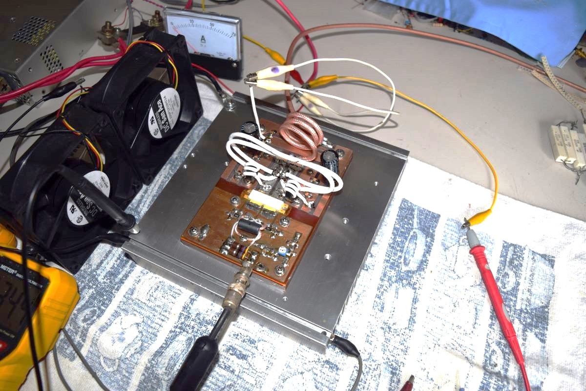
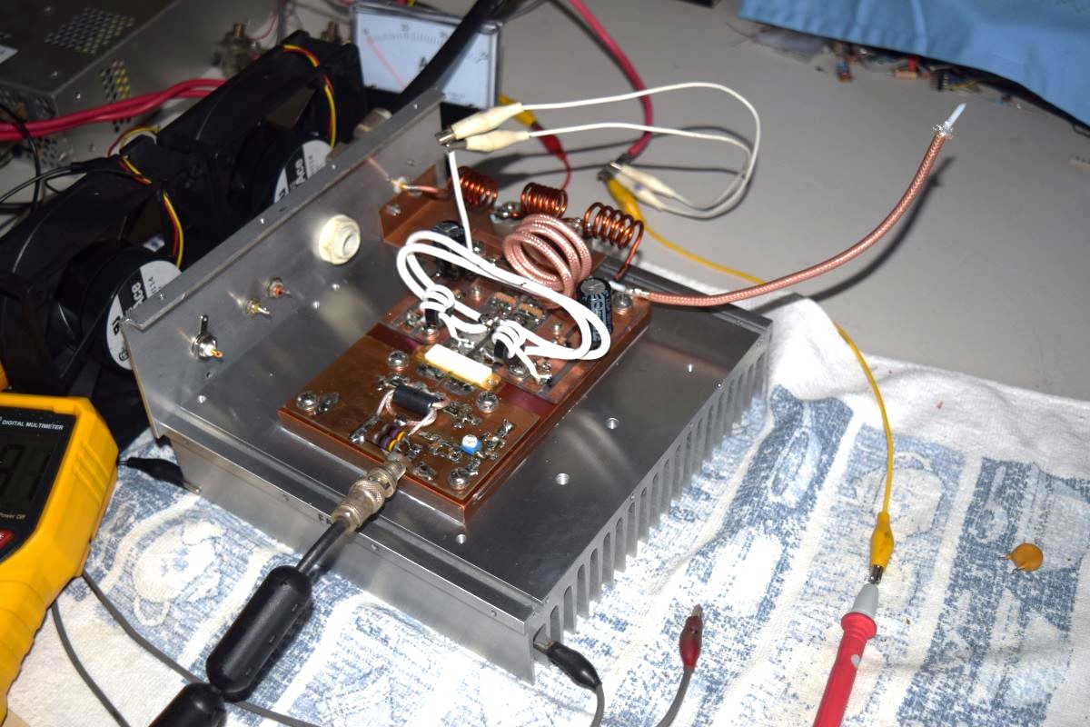
April 2024: After some thought about the desired outcome (a light-weight 6m DXpedition amplifier), I replaced the LDMOS device with a MRFX1K80H that was on hand, made a fresh/new output PC board, and built the older style W6PQL 6m output circuit using a 1:9 transmission line transformer from two pieces of 12 Ohm coax as is used very successfully in my 'main' 6m station amplifier.
As the old saying goes: "now we are cooking with gas". The power output on 6m was well over 1kW (a short test with the power supply turned up to 58V produced ~1.5kW RF output), with excellent apparent efficiency (>80%). There was also surprisingly good power and efficiency on 10m (note: even without ferrite loading, the output circuit is still broadband). However, the RF output from an unfiltered LDMOS amplifier contains high levels of harmonic power, so a LPF filter was added to 'clean it up' and determine the real performance at 6m with a more conservative 48V to 50V power supply setting.
After some adjustment of the LPF coils and adding a 'coax capacitor' across the PA pallet's output, the following results were obtained:
These figures are similar to the W6PQL 6m kitset PA (2014 - 2020 version) as used in my 'main' 6m station (50V, 30A, 1050W, 70% efficiency).
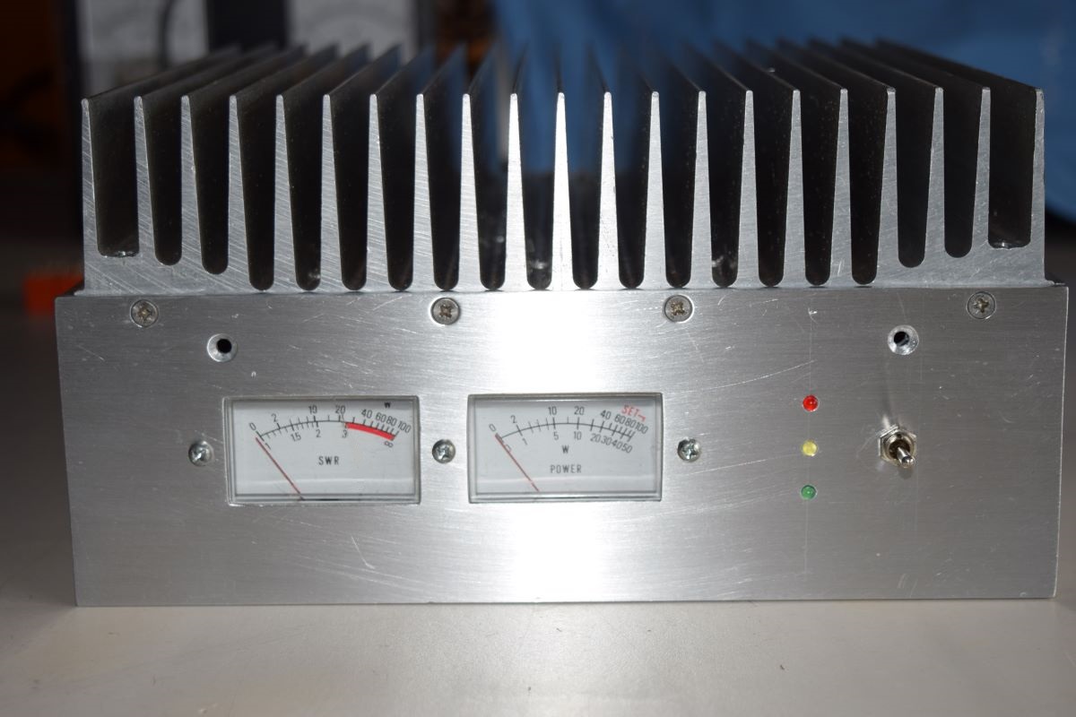
Not surprisingly the output at 10m was now poor due to the mismatch in the 6m LPF (~500W with very low efficiency). However, having obtained the primary goal (good power and efficiency at 6m), I'll continue to 'box up' the amplifier with cooling fans, relay switching, metering, etc.