ZL1BPU LF Station
-
Station Description
Exciter
 ZL1BPU LF Exciter (see details).
- Direct Digital Synthesis (DDS), 200mV p-p sinewave into 50Ω, 0 to 500kHz.
- Operates CW, QRSS, DFCW, Sequential MT-Hell, QRS Feld-Hell and JASON, either PC controlled or from internal beacon.
- RF OUTPUT (transmitter drive) and SYNC (modulator) are keyed. Envelope follows the SYNC and 'Carrier ON' LED
- Stability better than 10ppm 0° to 70°C, frequency resolution 0.08Hz. Commanded frequency always <1Hz error at all times.
- Exciter is powered by 12V supplied by transmitter.
Transmitter
Southern Avionics SC1000 (see details).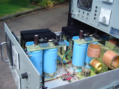
- One drawer of a Southern Avionics SC1000 DGPS USCG Dual Transmitter.
- Two 500W class D modules, each adjustable 25 - 500W at modulator.
- Each module has its own Class S modulator, 2kHz bandwidth for AM or CW envelope shaping.
- Each module operates up to 105V at 5A, and with combiner provides 1000W RF out.
- Common drive to both modules, sine to TTL level conversion and envelope shaping.
- Monitor circuits for Voltage, Current, Forward and Reverse Power.
- Fault detection for all fuse and suppy failures. Very robust.
Antenna and Loading Coil
Marconi Tee Vertical Antenna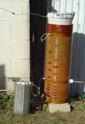
- Top wire 70m long, running NW/SE. centre (feed) point 8m, ends about 5m above ground.
- Feed wire / radiator 20m long, sloping at right angles to top wire.
- Top wire is high tensile galvanised fencing wire. Feed wire is 24 AWG insulated appliance wire.
- Three in-ground bare copper radials ranging from 10m to 20m length, plus one 24 AWG 40m surface wire under feed wire.
- Two bonded earth spikes at centre point of radials.
Loading Coil
- 300mm diameter, over 1m high. Lower section is bifilar wound Litz wire, upper section 12 AWG appliance wire.
- Total inductance 1.95mH with unloaded Q=260, consisting of original loading coil and 10 litre bucket of wire.
- Bucket is at hot end of coil and adjusted with wedge to provide series aiding.
- Loading coil is grounded adjacent to shack at centrepoint of radials.
- Loading coil tapped for 50Ω transmitter feed at eight turns.
- Original 8-turn shorted turn variometer provides 5kHz fine tuning, while wedge gives about 20kHz range.
- Further tuning adjustment via taps on lower (original) coil.
Tuning Technique
- Homebrew Impedance Bridge inserted at feed point to loading coil, driven directly by LF Exciter at 1W.
- Antenna can be swept using LF Exciter in shack with admittance bridge and oscilloscope detector.
- Complete system right through from Exciter to the antenna can be frequency swept by the Exciter.
- Computer controlled sweeping, T/R and mode switching and operating frequency adjustment.
- Final high power adjustment made at 50W level prior to careful power level increase, watching
for arcs, sparks and smoke from unexpected places!
The large coil on the right is the 181kHz loading coil, with glass-fibre former and bifilar Litz winding.
Where you see the white loop at the top left, the bottom of the bucket-of-wire top section connects to the top of the big coil. The top of the bucket feeds the antenna.
Despite its appearance, the bucket-of-wire has very high Q and low stray capacitance.
Note the tuning wedge behind the bucket on the right.
The small coil (a mere 300mm long!) on the ground to the left of the monster is the ceramic former 500kHz loading coil with solid 4mm silver plated wire,
waiting for approval to use the 600m band.
Receiving System
Receiver A
- Harris RF-505A receiver, using Hewlett-Packard 5065A Rubidium Standard as reference. Operates 5kHz to 30MHz with sub-Hz frequency accuracy.
- Active whip antenna, 500mm whip and remote preamp.
- 500kHz low pass filter between the whip and the first preamp transistor, which is a J310.
- Active whip is mounted 7m up, well away from trees, and 10m from the house.
- Antenna powered by battery via coax, and output is transformer coupled to receiver to avoid ground induced hum.
- System useful down to 8kHz, as below that the hum is excessive. Lowest received signal 10.24kHz.
Receiver B
- Icom RC-R71, modified with improved filters and crystal heaters for better stability. Operates 10kHz to 30MHz.
- Receiver is not as stable as desired, and with 100Hz frequency error at 180kHz. It also suffers from internal birdies,
but is very convenient to use.
- Antenna HF dipole, 5m passive whip, active whip (see above) or two-turn inductively coupled 3m diameter passive loop broadly tuned to 180kHz.
- System with loop is short of gain, but has very low noise. Needs a loop preamp. Lowest received signal 13kHz.
Receiver C
- Active whip (see above) coupled via telephone line transformer direct to PC sound card. Gives very good results 10kHz to 22kHz!
Copyright © M. Greenman 1997-2005.
All rights reserved. Contact the author before using any of this material.
BACK
HOME