This transmitter system is designed to provide unattended 24 hour operation for many years, and is therefore designed to be robust. It has two complete transmitters
and monitoring and control systems to allow the second transmitter to take over when the first fails. It also has no-break backup power. The unit is designed to transmit
carrier (A0) and MSK data (G1D) in the LF beacon band from 280 to 330kHz. For detailed information see the Specifications
page.
There are several modules in the 2m high rack. These will now be described. Follow the drawing on the right.
Transmitters
The top two drawers are the two transmitters.
Each consists of two independent 500W transmitter assemblies, operating with a common driver and monitoring circuit, and driving the output via a combiner.
Each transmitter drawer has its own power transformer, fitted in the base of the transmitter. The meters on the front allow overall Forward and Reflected RF power to be measured
on one instrument, and the supply voltage and current of each transmitter module on another. The other switches enable and disable HV AC and DC power,
the transmitter output and the monitoring system.
There is no means provided to operate the two 1000W transmitters into the same antenna. The monitoring system provides for switch-over, either manual or
automatic on failure, and the idle transmitter is routed to an output intended for a dummy load. It is possible to operate both transmitters at the same time, but
not both into the antenna. The switch-over circuitry is in the lower part of the rack. When controlled automatically, the RSIM transfers RF power from the selected
transmitter to the antenna, connects the deselected transmitter to dummy load, and enables the HV supply to the required transmitter. Drive is applied at all times.
Automatic Transfer/ RSIM Unit
Automatic switchover and monotoring is performed by the Automatic Transfer/ RSIM Unit, the third drawer in the rack. This uses a micro-controller and a large collection of I/O boards, monitoring
voltages and currents in both transmitters, the power supply, the charger and the antenna tuner. It provides a local RS232 serial link with telemetry information,
and a remote RS422
link with both telemetry and remote system control. The RSIM unit is operated from its own 115/230V AC supply, which is operated by an inverter if power fails. Power is removed
from the unit if the 24V drops below 19V.
The RSIM is a very complex unit, and since many of the boards in this unit have been damaged, it will probably not be redeployed. It is possible to run the transmitter drawers
independently (under local control) without this unit.
Load Centre / Battery Charger Unit
The fourth drawer from the top is the Load Centre / Battery Charger Unit. This consists of an immense SCR controlled and temperature compensated lead acid battery charger, which charges 12 batteries in series at 10A maximum. The high charge rate allows quick recovery from power failure, in case there is a further power failure. The output is 165V,
or 159V for float charge. The batteries used are deep cycle low leakage types, 50AH, so the transmitter will operate without AC power for perhaps 5 - 6 hours.
Inverter Unit
The fifth and final drawer contains the 50Hz inverter used to operate the RSIM Controller and various AC operated power relays when AC power has failed. It operates from the same +144V DC supply (12 batteries) as the transmitters. The inverter is capable of 1kVA semi-sinusoidal output.
AC Power and System Wiring
The open space under the drawers contains (at the back) the transfer and connection panel where all the relays are mounted, and where the main terminal blocks allow the system to be connected up. The relays are controlled by the RSIM, applying AC and DC power to each of the transmitters, and switching the antenna to the required transmitter. This equipment is mounted on the inside of the back panel, with the terminal blocks on the outside at the rear.
The three large power transformers are sited on the floor in the bottom of the transmitter. A plain panel would have covered the front of the open space. The batteries are sited
externally, and can have a temperature sensor fitted for accurate charge control.
Frequency control is provided by an external unit. This could be a simple carrier generator, or in the case of DGPS operation, is an MSK-modulated carrier. Presumably any narrow-band coherent phase constant amplitude mode could be used. A sinusoidal drive of 0dBm to +15dBm in 50 Ohms is required. The same drive can be used for both transmitters, or separate drive can be used. The drive frequency is the same as the output frequency, 280 to 330kHz. The transmitter is broadband, so the only changes required to operate within
that range are at the antenna.
In each transmitter drawer, a driver board conditions the incoming carrier into a fast-rise square wave, and converts it to TTL level. The TTL level signal drives both 500W modules within the drawer. Two common boards monitors Modulation, Forward Power and Reverse Power. Another board in each 500W module monitors the fuses in the modules. The outputs of these monitoring functions drive front panel lights and are sent to the RSIM Unit.
The driver board also controls the RF power level by adjusting the voltage supplied to the RF Boards by the Power Supply Modulators. While this could include an AC component
(audio modulation), in this model the voltage control is derived from a simple pot. The normal Power Supply Modulator output is 105V for 1kW output. A multiplexer circuit
controlled by the RSIM Unit switches resistors across the pot, and allows power to be backed off when the SWR is poor, and ramped up during automatic tests as power is applied.
Each module consists of five main boards:
- The RF Board (500W Class D switching amplifier with drivers).
- The Power Supply Modulator (Class S buck regulator / power amplifier).
- The AC/DC Power supply (contains the rectifiers and fuses and +12V regulator).
- The Low Pass Filter, a 5-pole Butterworth filter with a corner frequency of 500kHz.
- The Module Disconnect board which detects power supply and module fuse faults.
The power modules (RF and PS Modulator) have cast aluminium heat radiators on the top, which are cooled by a 24V operated fan on the front panel. Power Amplifier Current and Voltage in each module can be independently monitored. The combined RF output is monitored by a meter allowing forward and reflected power to be measured. Each transmitter can
be manually operated from the front panel, or control passed to the RSIM Unit. Separate switches are provided for HV power, LV power, RF output and Remote control over-ride.
Module outputs are at 50Ω impedance. Output from each 500W module, after passing through the LP Filter, is combined on the filter mother board with the other module output, via a pair of 1:1 baluns with secondaries in series. There is virtually no loss in the combiner, although it is not possible for this type of combiner to provide efficient operation once one transmitter fails or is disabled (in other similar models lacking dual transmitters, relays are used to short the unused module output). The combiner output passes through two current transformers, used to measure forward and reflected power and modulation level.
Connections to the transmitter drawer are fairly simple - either AC or DC HV and LV power (or both), RF drive, RF output, and a few control and status signals.
The original transmitter would have been a flat-top (Marconi Tee), probably 100m long, supported from two 30m poles. A single 30 - 50m lattice mast can also be used. Under this would be a ground mat consisting of at least 32 30m wires laid radially under the centre of the antenna.
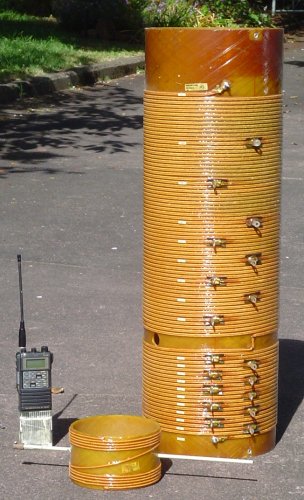
At the operating frequency, the antenna is very high impedance, and capacitive. A huge series coil, 1m high (see picture on right), provided with many taps and a variometer, is used to resonate the antenna at the operating frequency. At resonance, the feed point impedance is then very low (depends on the antenna height and the earth quality). This is then transformed back to 50Ω by a
tapped toroidal transformer. A further SWR measuring circuit is placed in the 50Ω feedline from the transmitter where it enters the tuner.
Because the ground and antenna characteristics vary with weather conditions, the antenna tuner will need to be adjusted frequently in order to maintain correct matching. Most of the variation is reactive, so the impedance transformer can remain fixed on the most appropriate tap. The reactive component is tuned out by automatic adjustment of the variometer, (in front in picture) which is mounted in the centre of the coil and being rotated, acts as an adjustable short-circuit inside the main series coil. The variometer motor drive is controlled by a circuit which determines the phase of the drive relative to that at the antenna, and adjusts the variometer angle to keep the phase the same, i.e. keep the antenna in tune.
All this circuitry is mounted in a large metal waterproof box at the base of the antenna. Output to the antenna is via a very large glass insulator at the top of the box on one side. Just below on the outside is a spark gap and the main system earth connection. The lightning strike which hit the installation completely destroyed this large box, the glass insulator, the spark gap, the variometer motor and all the boards inside the box. Fortunately the large coil and variometer, the matching transformer, the SWR meter and circuitry survived unscathed.