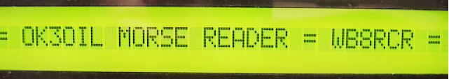
In recent months, I've been playing a bit with PICs. It's interesting business, but sometimes it's hard to figure out where it makes sense to apply the beasties. Francesco, IK3OIL, had an article in the August '99 QST on a Morse decoder using a PIC16F84. The circuit is pretty simple business, and has a lot in common with many other PIC/LCD projects. Indeed, it seems like there are lots of things that have a PIC and an LCD and some input circuit. For most of these projects the circuitry is about 90% common. Francesco has the information on his reader on his website.
I had agreed to do a presentation on PICs at the local radio club, and this seemed to be a nice project to show off. Further, a local friend, N8ERO, also had an interest in this circuit, so we set off to build our flavor of this thing.
I made a couple of choices on how this thing should be designed, based on stuff I had and what was cheap. First, it seemed to me that a nice, large display was a good thing for a CW decoder, and B.G. Micro has this gorgeous, 40X1, backlit LCD for like $7. The thing is 7" long so it makes a very nice display.
The BG Micro LCD1010 (Optrex DMC40131) turns out to be an extended temperature display, so I needed to provide a source of negative voltage to get good contrast. I ended up making a little charge pump from a 555, although something like an ICL7660 would probably have been a better choice, but I didn't have one. I did experiment with using the negative supply from a MAX232, which worked well, but seemed like gigantic overkill.
The 555 won't swing rail to rail and thus doesn't make the best charge pump in the world on a 5 volt supply. In fact, the result was marginal ... it was barely enough and probably wouldn't work on another display. N8ERO used cross coupled CMOS gates to drive a charge pump which worked a lot better.
I also have a more or less standard connection between the PIC and an LCD. I modified Francesco's program to use this connection. This allowed me to test the software on test circuits I had on hand before building the actual circuit board for the decoder. All of my projects involving PICs and LCDs use this same connection.
Francesco used a 567 to detect the CW note. I didn't have one on hand, and a trip to the local Radio Shack also came up empty. Rather than wait for mail order, I decided to press an NJM2211 into service. It took a little math and more experimenting, but it works pretty well. This part is overkill for this circuit, and I have no evidence that it works any better than Francesco's original. In fact, N8ERO used the 567 with pretty much the same result. He has some interesing improvement ideas on this part of the circuit that may turn out well... News at ll.
The final change was updating Francesco's CW table. Since there was plenty of memory available in the PIC, I added codes for all the CW characters I could find. (Did you know that in a few places, the same Morse character can represent different letters??) Also, since the LCD I had included both upper and lower case letters, I changed the display of some of the prosigns to make a little more sense. For example, I made the AS character display as a lower case 'w'.
If I recall, there was only one character that Francesco left out that I ever heard on the air. But for the club demo, I programmed another PIC to send a rather long message in Morse to the decoder, and having some special characters turned out to be nice for that purpose.
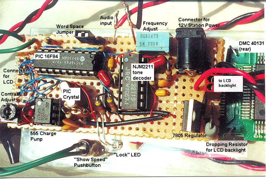 The unit is simple enough that I simply wired it point to point on a
perfboard. On the left is a 7X2 header (B.G. Micro ACS1019) which allows the entire circuit to
be plugged into the back of the LCD.
The unit is simple enough that I simply wired it point to point on a
perfboard. On the left is a 7X2 header (B.G. Micro ACS1019) which allows the entire circuit to
be plugged into the back of the LCD.
I chose a 7805, instead of a 78L05, because the backlight draws considerable current. That is also the reason for the 1 watt resistor.
You can click on the image at left to get a closer view.
 Rather than figure out how to cut a neat hole for the display, I simply
mounted the whole shooting match on a piece of Plexiglass which replaced the front panel in a
B.G. Micro CAS1003 case.
Our local hardware store sells off scraps of Plexiglass real cheap. Many
of these scraps are perfectly adequate for making front panels, bezels, etc., and
typically a piece big enough for a half-dozen panels costs a quarter or 50 cents.
OK, maybe it's not the most beautiful thing in the world!
Rather than figure out how to cut a neat hole for the display, I simply
mounted the whole shooting match on a piece of Plexiglass which replaced the front panel in a
B.G. Micro CAS1003 case.
Our local hardware store sells off scraps of Plexiglass real cheap. Many
of these scraps are perfectly adequate for making front panels, bezels, etc., and
typically a piece big enough for a half-dozen panels costs a quarter or 50 cents.
OK, maybe it's not the most beautiful thing in the world!
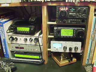 Here's the unit nestled between the other rigs at WB8RCR. Notice
the display matches that of the 2100H and 706MkII. (Although as you
can tell, I'm really not all that big on the cosmetics <g>, but
it might make a difference to someone whose shack is in the living
room).
Here's the unit nestled between the other rigs at WB8RCR. Notice
the display matches that of the 2100H and 706MkII. (Although as you
can tell, I'm really not all that big on the cosmetics <g>, but
it might make a difference to someone whose shack is in the living
room).
| Ok, for the curious, and because I don't have another picture of the shack on the site here: | |
|
Icom 2100H (Whiterook keyer hidden to the right) 2N2/40 MFJ 1274 TNC CW Reader Bencher paddle partly visible |
Icom 245 (for packet) Icom 706MkII MFJ 971 Tuner Square Brass Racer |
| Not shown: NC-20 (on loan), HTX-202, Icom Q7A, SMK-1, a couple of Fireball 40's, Pixie II, a really ugly homebrew 15 meter rig, and the K1 (on the way as of this picture). | |
Once I get the schematic drawn up, I'll post details of my modifications here as well as the PIC source modifications.