Use Those "Junk-Box" Chokes
By Sherman H. Hubelbank
Connecticut Telephone & Electric Corp.
Salvage those unidentified parts by running these
tests to determine their electrical characteristics.
Salvage those unidentified parts by running these
tests to determine their electrical characteristics.
When designing or building a voltage-regulated power supply with a choke input filter, the average experimeter or ham usually casts a furtive eye at his "junk-box" when he reaches the stage for the selection of the proper choke. Usually he has a number of iron-core chokes that appear to be physically large enough to carry the current needed, but not enough data is known to identify them, in order to build a good ripple-free, voltage-regulated power supply.
As a result, unless the builder can identify the choke by manufacturer and part number, his only recourse is to go to a catalogue and buy a choke that will meet his requirements. How- ever, by setting up a relatively simple circuit (see the schematic diagram) and following the procedures outlined, those "junk-box" chokes can be readily identified as to their electrical characteristics and, hence, can be salvaged.
To properly identify the electrical characteristics of an iron-core choke it is necessary that the basic characteristics of iron-core chokes and their effects upon power supplies be understood.
One of the most important characteristics needed to properly evaluate the suitability of a choke as an input filter for a voltage -regulated power supply is to know the relationship of inductance to the d.c. current flowing in the choke. This is important because as the d.c. current varies, so does the flux density of the core and, consequently, the inductance. This means that an iron core choke may have vastly different inductances under "load" and "no-load" conditions.
This characteristic may be utilized to good advantage in power supply filtering, because for most efficient filtering action the inductance should increase with a decrease in load current. It should be noted that a choke is called a swinging choke if the inductance is high at low values of direct current yet decreases markedly with increased direct currents. However, if the power supply has a bleeder resistor in parallel with the load, the importance of the ability of the choke to have its inductance increase with a decrease in load current diminishes, since there is always a minimum value of load current flowing through the choke.
At some point the choke will reach saturation as the current increases. This is due to the iron core becoming saturated, which decreases the permeability of the iron, and hence decreases the inductance of the choke. This, of course, determines the upper limit of usability of the choke under load conditions. In addition, it is important to know the maximum current the choke may carry without overheating.
It is also necessary to know the critical inductance of the choke, that minimum value of the input-choke inductance which prevents the d.c. output voltage from rising above the average of the rectified a.c. wave. This minimum value, the critical inductance, must be maintained at all currents, in order to prevent the filter from acting as a capacitor-input filter.
Therefore, it becomes evident that to properly use a "junk-box" choke it is necessary to have a plot of inductance versus load current. Then if the inductance range of the "junk-box" choke is proper for the design range of the filter needed, it may be readily used.
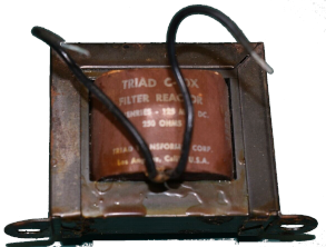
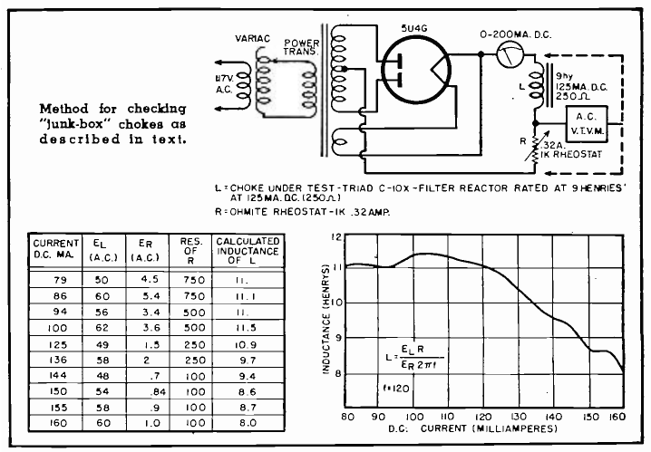
A relatively quick and comparatively simple procedure may be employed to plot this curve, using only a vacuum-tube voltmeter and an ammeter as test equipment. The test circuit should preferably be the full-wave rectifier of the power supply being built, with the choke and a high wattage rheostat in series across the output. (See schematic diagram.)
Hence, the normal equation for impedence:
Z = √ R2 + XL2
becomes
Z = XL
The current flow through L and R is
equal, consequently;
I = E/Z = EL/XL = ER/R
Solving for XL;
XL = ELR/ER = 2πfL
Therefore:
L = ELR/ER2πf
In actual use, vary the rheostat until the ammeter reads a low value of current. Measure the voltages across the rheostat and the choke with the vacuum-tube voltmeter, then measure the resistance of the rheostat. Substitute these values in the formula L = ELR/ER2πf and solve for L. (The value of f in a full-wave rectifier circuit is 120.)
Record this value of inductance and the current at which it was measured. Repeat this procedure until all the possible ranges of current that the power supply may require have been recorded.
When the curve has reached a point
where the inductance starts to level
as the current increases, the saturation point of the choke has been
reached. Since this determines the
upper limit of usability of the choke
under load conditions, this is also the
point at which the current rating of
the choke should be checked. Leave
the load connected for ten or fifteen
minutes, carefully observing the case
for signs of overheating. The choke
may get warmer than body temperature, but should not burn the hand or
get unduly hot. If the actual temperature of the choke is desired, fasten a
thermometer to the case with putty.
Be careful not to place the thermometer near the rectifier or any other
heat producing tube. The temperature
should be between 160° and 170° F.
(160° to 170° F is obviously in error. Typical modern chokes may be used at higher temperatures, but
old junk box chokes should be much cooler. A safer maximum temperature would be less than 130° F.)
The previously-described plot will accurately show the point of saturation and how the inductance of the choke varies under different load conditions, and from this it can be readily determined if that "junk-box" choke can be used in the power supply and whether it meets the design requirements.
REFERENCES
«Millman, Jacob & Seely, Samuel; "Electronics," McGraw-Hill Book Company.»
«Radio Amateur's Handbook," The American Radio Relay League»
Sherman H. Hubelbank
from Radio & Television News, October 1956, pages 176, 178 and 179.
© 1956, Gernsback Press