How to Use a Sound Card Interface with an Internal USB Sound Card
Introduction · The Signal · Hardware · PureSignal · Software · Operating · Technical · Contacts
The purpose of a sound card interface is to process signals between the HF transceiver and the PC when operating with sound card modes. Instead of using the PC's sound card, some sound card interfaces (such as the RIGblaster Advantage by West Mountain Radio) have a built-in USB sound card. This feature is especially useful when operating with soundcard modes requiring an additional sound card, making the PC's sound card available for use with these modes. In the link below, Mel Whitten, K�PFX, describes the use of a RIGblaster Advantage with FreeDV digital voice (after the PDF document is downloaded, see pp. 7-11).
K�PFX Article Link
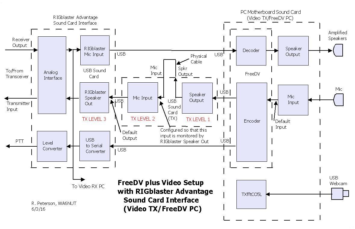
Figure 1 below shows the software signal flow diagram for the "default" FreeDV plus Video setup for the Video TX/FreeDV PC. Note how three sound cards (the motherboard sound card and two USB sound cards) are used in the setup. The TX USB sound card (used to set TX LEVEL 2 and TX LEVEL 3) must be configured for "input monitoring" (either as a built-in feature or by configuring through the Windows Sound driver). We'll discuss input monitoring in a paragraph below.
Figure 2 below shows a software signal flow diagram using a sound card interface, with a built-in USB sound card, connected to a PC for FreeDV digital voice (the setup used by K�PFX). Note that two sound cards are used in this setup (the PC's motherboard sound card and the internal USB sound card in the interface).
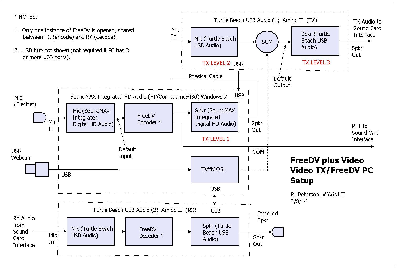
But a third sound card, as shown in Figure 3 below, is required for FreeDV plus Video. The TX USB sound card provides level adjustment (TX LEVEL 1 and TX LEVEL 2) of the FreeDV encoder output, which is summed with the video baseband signal at the RIGblaster Speaker output. These level adjustments control the FreeDV level with respect to the video level. The TX LEVEL 3 control (the RIGblaster Sound output) adjusts the level of the composite FreeDV plus Video signal.
Also note that the TXfftCO5L video software block is added to the PC, with a USB webcam connected at the input of the block. The Windows Sound Playback driver is configured with the RIGblaster USB sound card output as the Default output. This ensures that the baseband video signal will be summed at that output (the TXfftCO5L software design requires its output to be applied to the sound card output designated as the default). Click on the link below to download a detailed Software Connection Chart (in .XLS format) showing how to connect the blocks together as shown in Figure 3 below.
Software Connection Chart Link
In addition, the Windows Sound driver is configured for "input monitoring" of the TX USB sound card input by the RIGblaster USB sound card output. This ensures summing of the FreeDV baseband signal with the video baseband signal at the RIGblaster USB sound card output. You can find a discussion of "input monitoring" at the link below:
Input Monitoring Link
See the link below for instructions for setting the TX USB sound card for input monitoring (also see Notes 1 to 4 below).
Windows 7/8 Link
Note 1:Under the Windows 7/8 "Listen" tab, for the TX USB sound card, the "Listen to this device" checkbox is checked with the "Playback through this device" option left at the default "Default Playback Device" setting. Then click on the "Apply" button.
Note 2:The Windows Sound Playback Levels control for the RIGblaster USB sound card Speaker output is used for TX LEVEL 3.
Note 3: This scheme works only with Windows 7/8, because the input being monitored and the monitoring output are on separate devices (both Windows XP and Vista require that the monitoring output and the input being monitored reside on the same device).
Note 4: Because this scheme requires input monitoring between separate devices, USB sound cards with built-in input monitoring (such as the Turtle Beach Amigo II) cannot be used for the TX USB sound card.
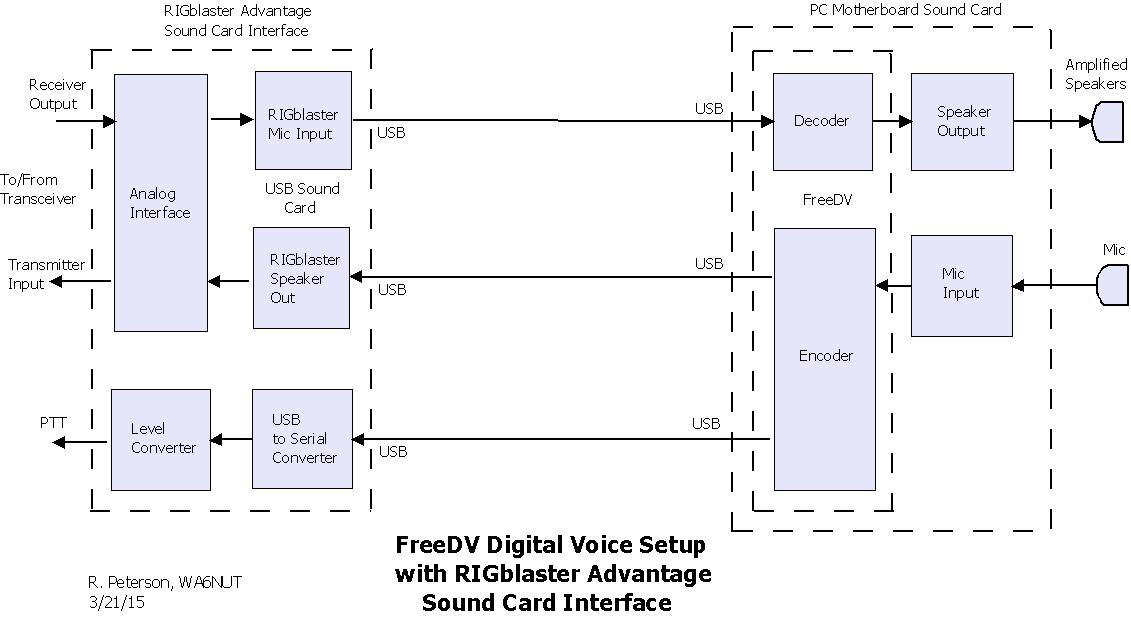
Figure 3 (below): Software signal flow diagram for FreeDV plus Video with RIGblaster Advantage. Although not shown, summing of the FreeDV baseband and video baseband signals is implemented similarly to the implementation in Figure 1. See text for a link to a Software Connection Chart giving details on how to connect the blocks in the diagram below.