>>>>>>>>>>>>>>>>>>>>>>>>>>>>>>>>>>>>>>>>>>>>>>>>>>>>>>>>>>>>>>>>>>>>>>>>>>>>>>
"If Stevie Ray Vaughan was a ham, he'd be pounding brass on a homebrew, qrp transceiver..."

| I have been doing the qrp "thang" since
late
November, 1994. At that time, I would "throttle back" my FT-101ee
to
around five watts or so. Prior to that, most of my cw
operating
was between 30 and 100 watts. I
have always
been intrigued with home built radios, but was a little intimidated with
schematics and parts procurement. In
the
back of my mind I kept seeing the article written by W7ZOI and K7TAU
about
"The Mountaineer-an Ultraportable CW Station". It was in an
August 1972
issue of QST. Boy did I want to do something like that. But
I
wasn't ready. Then one day, I took the soldering gun by the cool end and started to build. My first attempts were crude. The layout was messy and the hookup was sometimes a tangled mess. But it was a start into a very fascinating part of ham radio, very much like what I can only imagine the early days of wireless were like. With each project, I became more comfortable with laying out the parts, etching pc boards, getting parts, winding coils etc. What was really fascinating was I was learning about radio and was starting to use some of the theory I had memorized for upgrading to Advanced and Extra Class Hamster. Right now, I have qrp rigs for 40m, 30m and 20m--all from different designers, as well as homebrew test equipment for putting together my flea powered radios. My antenna is just a 33 foot piece of metal, set vertically and matched by a tuner. I would like to have a better radiator, but this is all I can manage where I live. I don't work much dx, but that's fine, I never did much of that chase anyway...I just enjoy making a contact with my own stuff!! |

|
|
|
|
|
|
|
|
|
|
|
|
|
|
|
|
|
|
|
|
|
|
|
|
|
|
|
|
|
|
|
|
>>>>>>>>>>>>>>>>>>>>>>>>><<<<<<<<<<<<<<<<<<<<<<<<<
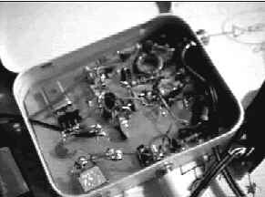
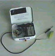
My favorite homebrew rig is my 40m transceiver. I found the schematic in a back issue of QST and thought it would be a challenge to build. The fellow that designed it is NN1G. I had read many comments about it in various qrp publications and it seemed like most of the folks that had built one really thought it had an excellent receiver and a very stable vfo. I got most of the parts for it from Dans Small Parts. I built the receiver first, using double sided copper clad board---the top acting as a ground and the bottom I had cut soldering islands with a exacto knife. Parts that weren't grounded, I drilled and countersunk the top and soldered to the pad on the bottom. Other than a few minor wiring mistakes, the receiver worked the first time, and was spot on frequency! I built the transmitter on another board, in the same manner as the receiver. It worked the first time also. I made a few mods to suit my needs, and added a Tick-1 keyer chip inside the xcvr cabinet to give me the option to use a keyer during contests.
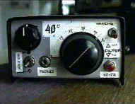 |
40m superhet xcvr (Pride and Joy) |
>>>>>>>>>>>>>>>>>>>>>>>>>>>>>>>>><<<<<<<<<<<<<<<<<<<<<<<<<<<<<<<<<<<
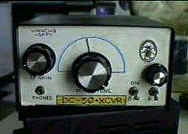
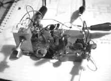
The next rig in the family is my 30m dc transceiver. It is truly the "Heinz 57" of the three. The rx portion is from a Doug DeMaw design which I modified and the vfo is based on a Wes Hayward concept. I made the vfo for 5.05 mhz and used a doubler to get it up to 10.1 mhz. The transmitter is from many sources. The board were made in the same fashion as the 40m rig. Output is about 1.25 watts and it is housed in a larger cabinet than the 40m rig. The receiver works well (after some troubleshooting) and I have made many contacts with it. It draws more current than the 40m rig, and I don't think I'd use it in the field. There are very many parts in this rig....
| 30m direct conversion xcvr |
 |
>>>>>>>>>>>>>>>>>>>>>>>>>>>>>>>>><<<<<<<<<<<<<<<<<<<<<<<<<<<<<<<<<<<
The last rig is one designed by w6emt- the nw 80/20. I chose 20m and only built the receiver portion. This was a pretty hefty project, although the 30m DC rig was pretty major too! Layout was the same as the others except this time I etched the islands. That was my first attempt at that process. I am happy to say that I am a lot better at it than at the time of this project! The radio worked OK but as usual, there was some tweaking needed in order for to work right. There is quite a loud hiss in the audio which according to some of the crew on the qrp-l, is caused by my 386 chip. I tried everything that I had read concerning the hiss problem for that particular device, but nothing seemed to work like I had hoped. Replacing with a quieter chip is the answer. The transmitter is the basic vxo circuit- power about 1 watt. I have made about 10 qso's and most of those were during a contest. In all honesty, 20m has never been a favorite with me, so I haven't really spent the time getting this rig to in a-1 shape. My 40m rig has spoiled me, and I kind of hoped everything worked like it! I think if I do anything, it will be to finish the transmitter section like it was meant to be, and not be rock bound as I am now...
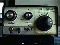 |
20m superhet trans-rcvr |
>>>>>>>>>>>>>>>>>>>>>>>>>>>>>><<<<<<<<<<<<<<<<<<<<<<<<<<<<<<
Here is what I have been messing with lately....
 |
| This is a 40m vxo that I am bread boarding. I really don't need anything like this but its just fun knocking things together. Output is about 1 watt and the xtal swing is about 4 khz. I may build a vfo and delete the xtal and then build another receiver for 40m. to go with it. Hey, that's what it's all about!! The first time I built a little oscillator like this, was back in 1996. In fact, my real building career started from a simple circuit like this....and yes you can have many qso's with 1 watt. |
>>>>>>>>>>>>>>>>><<<<<<<<<<<<<<<<<
40m
vxo-revised
| I decided to change the vxo around a bit. I wasn't really happy with the design. I added a couple of chokes in series and a capacitor in parallel to give more swing to the xtal. I now get about 8 khz. swing. Also added a keying switch. This now is more like the early vxo transmitters I built when I first got started. None of the schematics are my designs---they are made up from many plans I got from various publications. I still haven't decided what I am going to do with it....maybe a qrp rig for hiking or camping..... |

| Well, I decided to go back to the original Pixie2 design, with a few mods that I had found on the Internet. I still have not tried working anyone with it. Power out is pretty low and it would be a real challenge for me to work someone with the antenna set-up here on the Island. Below is the schematic and some photos...sorry I can't get better detail with my pictures. |

| Well it has been revised again! But the best thing is I finally worked a few hams with the Dixie Pixie. On May 23, 2000 running 400mW, I worked W1PID. Then on May 25, 2000 running 250mW, I worked K1QM and again, W1PID. I still have not got the offset to my liking, but rubbering the xtal during rx helped. Also, I am still getting bleed thru from SW broadcast stations. This has been a fun project. One thing to note is my Dixie Pixie is based on several Pixie's I have seen in various publications. I am having fun trying a little of this and a little of that from other designs. That is the beauty of homebrewing! |
 |
 |
>>>>>>>>>>>>>>>>>>>>>>>>>>><<<<<<<<<<<<<<<<<<<<<<<<<<<
July
16,2000---Latest
project
 been wanting
to
build something here lately but because of other things going on,
just
didn't find the time. I order parts for building the
SST-40, but
was not able to get the xtal's. Since then, I made another order
to
Mouser and the rest of the parts should be here soon. In the mean
time,
we had a break in the weather and I couldn't get the "building bug" out
of
my head. So yesterday, after a week of reviewing designs from my
reference
library, I decided on a DC receiver for 40m. It is based on the
Micromountaineer
from the April 2000 issue of QST (w7zoi) except I built a vfo for it
instead
of being rockbound. The vfo design uses diodes for tuning in
place
of the variable cap.
been wanting
to
build something here lately but because of other things going on,
just
didn't find the time. I order parts for building the
SST-40, but
was not able to get the xtal's. Since then, I made another order
to
Mouser and the rest of the parts should be here soon. In the mean
time,
we had a break in the weather and I couldn't get the "building bug" out
of
my head. So yesterday, after a week of reviewing designs from my
reference
library, I decided on a DC receiver for 40m. It is based on the
Micromountaineer
from the April 2000 issue of QST (w7zoi) except I built a vfo for it
instead
of being rockbound. The vfo design uses diodes for tuning in
place
of the variable cap. 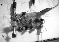 The design is based on things I found in
Demaw's
W1FB's QRP and Design Notebooks. The front end (I think that is
what
you call it) is from a design from Monty, N5FC. Look at his
little
receiver on his web page. I had all of the parts
needed
in my junk box and even had the torroids already made up from a past
project.
After a few "hot" parts, causing a zener to fry, I started to receive
some
honest to goodness ham radio stuff.... Tuning is still pretty
sensitive,
but hopefully will be able to clear that up and maybe make up a nice
etched
board for it. Right now, it is pretty ugly looking. Sorry
about
the quality of the pictures. They aren't the greatest but
at
least you get the "picture". The schematic is down below.
The design is based on things I found in
Demaw's
W1FB's QRP and Design Notebooks. The front end (I think that is
what
you call it) is from a design from Monty, N5FC. Look at his
little
receiver on his web page. I had all of the parts
needed
in my junk box and even had the torroids already made up from a past
project.
After a few "hot" parts, causing a zener to fry, I started to receive
some
honest to goodness ham radio stuff.... Tuning is still pretty
sensitive,
but hopefully will be able to clear that up and maybe make up a nice
etched
board for it. Right now, it is pretty ugly looking. Sorry
about
the quality of the pictures. They aren't the greatest but
at
least you get the "picture". The schematic is down below.
 |
| At my work bench, I use a Micronta FET VOM, a Weller SP-23 soldering gun with a homebrew heat output adjustment and an Autek RF Analyst. I also have a homebrew adjustable power supply. The remainder of the test gear I use is homebrew. I have a SWR-PWR meter, a Audio oscilator and a RF probe. |
 |
swr-pwr
|
| r.f.probe |  |
 |
|
>>>>>>>>>>>>>>>>>>>>>>>>>>><<<<<<<<<<<<<<<<<<<<<<<<<<<<<<<<<<<<
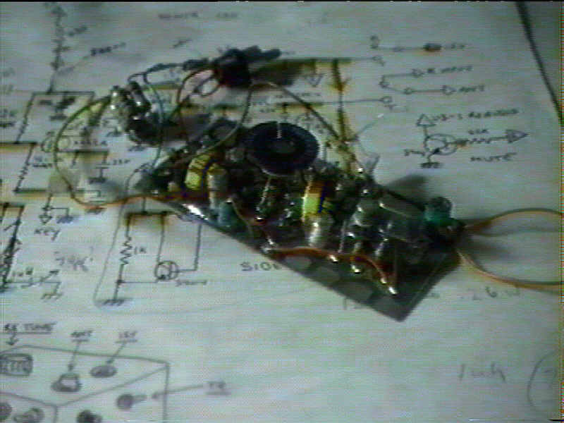
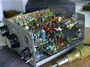
Here are some interior shots of the little homebrew rigs I have put together
| 40m superhet xcvr |
 |
 |
30m direct- conversion xcvr |
| 20m superhet tx-rcvr |
 |
 |
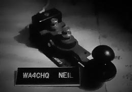
custom paddle |
>>>>>>>>>>>>>>>>>>>>>>>>>>>>>>>>>>>><<<<<<<<<<<<<<<<<<<<<<<<<<<<<<<<<<<<
How
about a few links???
****George's Place--K9GDT****
****Ameteur Radio & DX Reference
Guide--AC6V****
****Middle Peninsula Amateur Radio Club****
****The
Alaska
QRP Club ****
****Visit
Hell****NB6Z
Digital Page****
****Visit my Dads page, W4RZB****How about his old QSL???****
****NL7DS QRP Web Site**** K3WWP's CW/QRP Site***
****N5FC's Ham
Radio Page****
****Gloucester Area
QRP and
Homebrewers Club****
![]()

click here to
sign the guestbook
send me some feedback about this site...(mycallsign)(at)netscape.net
hint...my callsign is wa4chq
RNT-1999/2k