|
A Jumpered Dipole Antenna
My original plan for a portable HF antenna for the
trailer was to do something different and build a jumpered dipole.
Then I decided I didn't have time nor the energy to make one before
Field Day 2009 and bought a G5RV Jr instead. Upon reading the
instructions that came with the G5RV Jr, however, I found that any
metal near the wire feed line would detune the antenna. It further
specifically stated not to use it with a metal antenna pole, which I
would have on the trailer. Yes, I could make do with it by taking
additional PVC pipes for masting, but why go to all that trouble? It
was time to go back to "Plan A".
A jumpered dipole offers low loss (assuming negligible
resistance across the jumpers), coax feed, and in most conditions an
uncompromised bandwidth and a standard dipole pattern without a
tuner. The major disadvantage is that you need to lower the antenna
each time you switch bands. This can be difficult at night. It may
not a good choice for rapid or frequent band changes, but for a
portable antenna used as an Inverted "V" for Field Day, it
should work fine. I already had the set-up built for lowering the
center of the "V" from the mast.
I like the idea of having a full half-wave dipole for
the 40, 20 and 10 meter bands, and with the MFJ-949E antenna tuner I
use for portable operation, the antenna will also work on 30, 17, 15,
and 12 meters for occasional DXing if/when the HF bands improve. The
antenna I chose to build was patterned after one shown in the
November 1996 QST magazine. I found the plan to be very close to what
I had envisioned when I contemplated building the jumpered dipole earlier.
Materials List:
Making the insulator/jumper assembly
Before laying out wire for the antenna, I made the
insulator/jumper assemblies. There are several was to make a jumper,
and most will be lighter in weight than what I made. I even thought
of using Anderson Power Pole connectors on wires. They certainly
would be light weight, but possibly difficult to connect in the dark.
The original plan called for pieces of flat Plexiglass
for insulators. I didn't have any on hand, but I did have 1/2"
inside diameter PVC water pipe. Four 3" pieces were cut from it
and drilled for #8 bolts.
After pushing the bolts through the PVC pipe and
fastening them with nuts, I marked the aluminum for drilling. After
drilling the two holes for the bolts, I used a drill, hacksaw and
file for finishing the notches.
No flat washer was used on the outside of the
notched end between the jumper bar and wing nut. The #8 washers are
so thin that it would take a lot of time to fiddle with getting the
metal bar between them when lengthening the antenna. It 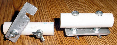 would
be almost impossible in the dark. This way, all that needs to be
done is the turn the jumper assembly until the bolts are upright, and
the single washer on the inner side of the metal bar drops into place
against the regular nut. would
be almost impossible in the dark. This way, all that needs to be
done is the turn the jumper assembly until the bolts are upright, and
the single washer on the inner side of the metal bar drops into place
against the regular nut.
To change to a lower band, let down the antenna,
loosen the wing nut on the unnotched end slightly, loosen the wing
nut on the notched end of the metal bar, turn the assembly so the
bolts are pointed upward, flip the notched bar onto the bolt, and
tighten both wing nuts. It's easy, even in the dark. Make the same
adjustment to the other half of the antenna, and then raise the
antenna back into position. To go higher in frequency,
"unlock" the appropriate notched end on each leg of the antenna.
Your first reaction might be, "Wow! I would have
to lower both sides of the dipole to change bands." You would be
correct. That's why I have chosen to use the antenna in the Inverted
"V" configuration.
I checked to see what the length of each antenna leg
(connector included) should be, then started out with additional wire
on each leg. It is easier to cut wire off then to add it. An MFJ-249B
antenna analyzer was used to determine the length of each individual
dipole section, starting with the band highest in frequency and
moving outward to the lower bands.
If you are unsure what frequency
to cut the antenna for on a given band, cut it to cover the SSB
portion you intend to work. You can always dangle a short piece of
wire off the end of the section in use to bring the antenna to
resonance on the lower frequencies. If you want to expend the extra
effort, you could make complete additional sections of wire for the
lower frequencies to substitute when necessary. I'm not that much of
a purist.
We did not have time to test the
antenna with a rig, however the antenna analyzer showed full band
coverage on 10 meters at 2:1 SWR across the entire band; coverage of
the entire 20 meter band using 14.180 for the center frequency and
both band edges at 2:1 SWR; and all but 8 KHz of the 40 meter band
with band edges showing an SWR at 2:1.
Used with the tuner, the antenna
performed very well on 40 and 20 meters during the 2009 Field Day
event in June.
Things I would do differently next
time? I am not a fan of 14 gauge stranded wire. It is too flexible
and tangles easily. I would use solid wire, or at least 12 AWG
stranded wire. I would also use a flat base for the insulator/jumpers
rather than PVC pipe. It is difficult to keep the bolts tight on a
rounded surface. Using 2" rather than 1-1/2" bolts with the
PVC pipe insulators would provide more usable threads when changing
the jumpers.
(Continued on next page) |

