Parts:
- 2 each 680 pf,
- 2 each 1500 pf
- 2 each 3 uh inductors,
- 1 each 3.5 uh inductor
(try to get 5% small
disc ceramic capacitors),
(see note).
using T25-2,
powered iron toroid cores .25 diameter mix #2.)
Receiver Modifications |
| Back to
Bernie's Bench |
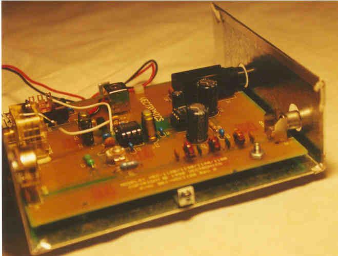
Modified Receiver Kit I recently purchased
a Vectronics 80 M receiver kit to experiment with the NE 602 OSC/Mix IC.
I was amazed how well the receiver worked. However, the first problem I
encountered was 40M SW broadcast interference. The second harmonic of the
local osc in the receive is present and caused direct conversion (reception)
of strong 40 M signals. This cannot be filtered as it is internal to the
chip. However, by the addition of input selectivity to the receiver this
problem can be eliminated. I built a seven element Chevyshev low-pass filter
C in/out using standard capacitor values. (See Radio Amateur Handbook Chapter
30, references, Seven Element Chevyshev filter C in/out standard capacitors
, filter #64.) I chose this model because I wanted to pass the 80 M CW
3.7 Mhz and reject the second harmonic around 7 Mhz. This filter rejects
that well over 40 db. Presto! The 40M interference disappeared.
|
| CONSTRUCTION:
Parts:
(try to get 5% small disc ceramic capacitors), (see note). using T25-2, powered iron toroid cores .25 diameter mix #2.)
|
|
| That core has a 100 turn winding index number of 34.
Using the formula: Turns=square root (target L in uh/index number) or T=100 x Square root (3/34) T=100 * square root (.00882) T=100 * .297 T=29.7 turns a 3 uh coil = 30 turns
|
||
DIAGRAM:
 |
||
| INSTALLATION:
I installed the parts right on the receiver circuit board, using the circuit trace coming from the antenna jack going to the RF gain control. Near the antenna jack I cut the trace and removed a 1/8" length of copper in three places approximately one half inches apart. Then drilled holes for wire leads of capacitors and inductors, also holes for ground side of capacitors. Use a small drill, just big enough for the leads to pass through. Scrape off the solder mask (coating) in the area to be soldered. |